Horizon 8 on Azure VMware Solution Architecture
This chapter is one of a series that make up the VMware Workspace ONE and VMware Horizon Reference Architecture, a framework that provides guidance on the architecture, design considerations, and deployment of VMware Workspace ONE® and VMware Horizon® solutions. This chapter provides information about VMware Horizon 8 on Azure® VMware Solution. A companion chapter, Horizon on Azure VMware Solution Configuration, provides information about common configuration and deployment tasks for VMware Horizon on Azure VMware® Solution.
Introduction
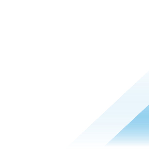
VMware Horizon for Azure VMware Solution (AVS) delivers a seamlessly integrated hybrid cloud for virtual desktops and applications. It combines the enterprise capabilities of the VMware Software-Defined Data Center (SDDC), delivered as infrastructure as a service (IaaS) on AVS, with the market-leading capabilities of VMware Horizon for a simple, secure, and scalable solution. You can easily address use cases such as on-demand capacity, disaster recovery, and cloud co-location without buying additional data center resources.
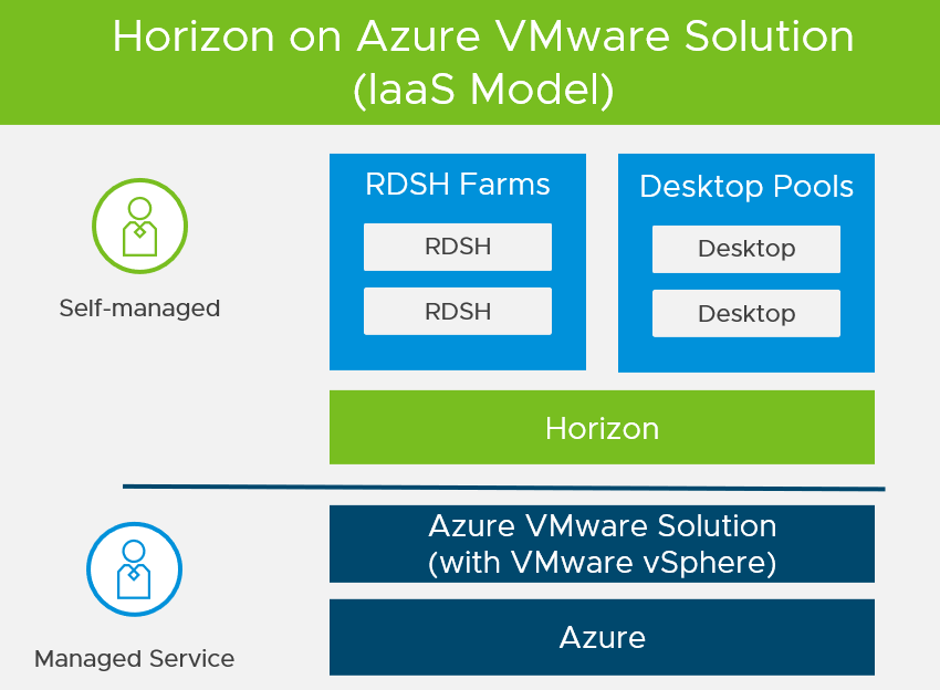
Figure 1: Horizon on Azure VMware Solution Overview
For customers who are already familiar with Horizon or have Horizon deployed on-premises, deploying Horizon on Azure VMware Solution lets you leverage a unified architecture and familiar tools. This means that you use the same expertise you know from VMware vSphere® and Horizon for operational consistency and leverage the same rich feature set and flexibility you expect. By outsourcing the management of the vSphere platform to Microsoft, you can simplify the management of Horizon deployments.
Note: Horizon 8 2006 and later can be deployed on Azure VMware Solution. Horizon 7.13 cannot be deployed on Azure VMware Solution.
For details on feature parity between Horizon on-premises and Horizon on Azure VMware Solution, as well as interoperability of Horizon and Azure VMware Solution versions, see the VMware Knowledge Base article VMware Horizon on Azure VMware Solution (AVS) Support (80850).
The purpose of this design chapter is to provide a set of best practices on how to design and deploy Horizon on Azure VMware Solution. This chapter is designed to be used in conjunction with Horizon documentation and the Azure VMware Solution documentation.
| Important | It is highly recommended that you review the design concepts covered in the Horizon 8 Architecture chapter. This chapter builds on that one and only covers specific information for Horizon on Azure VMware Solution. |
The VMware Cloud Tech Zone contains useful resources on Azure VMware Solution to give foundational information on the platform.
Deployment Options
Azure VMware Solution allows you to create vSphere Software-Defined Data Centers (SDDC)s on Azure. These SDDCs include VMware vCenter Server for VM management, VMware vSAN for storage, and VMware NSX for networking.
There are two possible deployment options for Horizon on Azure VMware Solution (AVS):
- All-in-SDDC Architecture - A consolidated design with all the Horizon components located inside each SDDC. This design will scale to approximately 4,000 concurrent users per SDDC. Each SDDC is deployed as a separate Horizon pod.
- Federated Architecture – A design where the Horizon management components are located in Azure and the Horizon resources (desktops and RDS Hosts for published applications) are located in the AVS SDDCs. This design is still limited to approximately 4,000 concurrent users per SDDC but supports Horizon pods that consume multiple SDDCs. Because this design places the Unified Access Gateway appliances in the Azure Platform and in front of the NSX edge appliances in the SDDC, standard Horizon limits will apply to the size of the Architecture. It is scaled and architected the same way as on-premises Horizon. See the VMware Configuration Maximum Tool for details.
Note: 4,000 concurrent users per SDDC is given as general guidance. The volume of network traffic to and from the virtual desktops or published applications, and the throughput into and out of the SDDC, has an impact on the number of sessions per SDDC possible. Testing should be carried out to determine the number of sessions that can be supported based on the actual workload and network traffic.
All-in-SDDC Architecture
In the All-in-SDDC-based deployment model, all components, including management, are located inside the Azure VMware Solution Software-Defined Data Centers (SDDC).
Due to current limitations of the NSX-T Edge gateways and the placement of the Unified Access Gateways, the All-in-SDDC-based model is only recommended for small/medium scale deployments (4,000 desktops or less).
The following figure shows the high-level logical architecture of this deployment model and all the management components inside the SDDC. The following figure shows the high-level logical architecture of this deployment model with all the management components in the Azure VMware Solution SDDC.
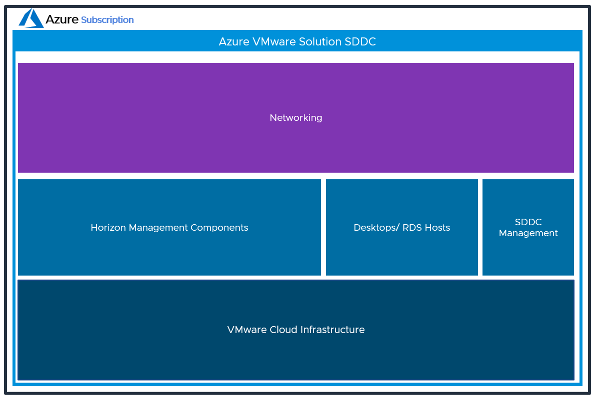
Figure 2: Logical view of the All-In-SDDC Architecture of Horizon on Azure VMware Solution
In this design, because all management components are located inside the SDDC, this can potentially lead to protocol traffic hairpinning. If using global entitlements as part of cloud pod architecture or using a single namespace, the user could be directed to either pod. If the users’ resource is not in the SDDC that they are initially directed to for authentication, their Horizon protocol traffic would go into the initial SDDC to the Unified Access Gateway, then back out via the NSX edge, and then be directed to where their desktop or published application is being delivered from. The result is a reduction in achievable scale due to this protocol traffic hairpinning.
For this reason, Horizon Cloud Pod Architecture is not recommended with the All-in-SDDC Architecture on AVS.
With the All-in-SDDC architecture, each SDDC represents a separate Horizon pod and would have a unique name (for example, pod1.company.com). Universal Broker or Workspace ONE Access can be used to present users with a single initial FQDN for authentication and resource choice. Alternatively, users would connect directly to each individual pod’s FQDN with the Horizon Client.
Federated Architecture
In the federated deployment model, all Horizon management components are located in Azure. The desktop / RDS capacity is located inside each Azure VMware Solution SDDC.
With the Federated Architecture, a single Horizon pod can be scaled to include multiple SDDCs and address large-scale deployment needs. The following figure shows the high-level logical architecture of this deployment model with all the management components in Azure.
Figure 3: Logical view of the Federated Architecture of Horizon on Azure VMware Solution
Architectural Overview
The components and features that are specific to Horizon on AVS are described in this section.
Components
The individual server components used for Horizon, whether deployed on Azure VMware Solution or on-premises, are the same. See the Components section in the Horizon 8 Architecture for details on the common server components.
Software-Defined Data Centers - Azure VMware Solution Private Clouds
Azure VMware Solution allows you to create vSphere Software-Defined Data Centers (SDDCs) on Azure. These are also referred to as Azure VMware Solution Private Clouds. See Azure VMware Solution private cloud and cluster concepts. Throughout this document, we will use the term SDDC.
These SDDCs (Azure VMware Solution Private Clouds) include VMware vCenter Server for VM management, VMware vSAN™ for storage, and VMware NSX® for networking.
You can connect an on-premises SDDC to a cloud SDDC and manage both from a single VMware vSphere Web Client interface. Azure VMware Solution is a native Azure service and has native integration with Azure’s broad ecosystem of services including DR, Backup, Azure Active Directory, Azure management and security services, Azure Cognitive Services, and more. For more information, see the Azure VMware Solution documentation.
After you have deployed an SDDC on Azure VMware Solution, you can add this SDDC as capacity to your Horizon Connection server to run your VDI workloads such as Desktops or RDSH hosts. This enables Horizon customers to outsource the management of the SDDC infrastructure to Microsoft. There is no requirement to purchase new hardware, and you can use the pay-as-you-go option for hourly billing on Azure VMware Solution. See Azure VMware Solution pricing.
Azure Components
- vNet and subnets for Management and DMZ networks. See Network Configuration.
- Express Route Gateway for Connecting AVS SDDC to VNET
- Azure Load Balancer (ALB) for External /internal Load Balancing
- Azure Traffic Manager (ATM) for Global Load Balancing
Management Components
The management components for the SDDC include vCenter Server and NSX-T.
The management interfaces are available to customers to manage vSphere and NSX-T. See the Tutorial: Access an Azure VMware Solution private cloud for details.
Compute Components
The compute component includes the following Horizon infrastructure components:
- Horizon Connection Servers
- Unified Access Gateway appliances
- App Volumes Managers
- Virtual Desktops
- RDSH Hosts
- Database Servers
- App Volumes
- Horizon Events Database
- Horizon Edge Gateway Appliance (used when connecting to Horizon Cloud Service – next-gen)
- Horizon Cloud Connector Appliance (used when connecting to Horizon Cloud Service – first-gen)
- File shares for user data and VMware Dynamic Environment Manager™ configuration data
NSX-T Components
VMware NSX-T™ Data Center is the network virtualization platform for the Software-Defined Data Center (SDDC), delivering networking and security entirely in software, abstracted from the underlying physical infrastructure. See the Understand NSX-T activity path for more information.
The maximum number of ports per logical network is 1000, you can also use multiple logical networks per pool with Horizon by leveraging the Multi VLAN functionality.
- Tier-0 router – Handles Internet, route or policy-based IPSEC VPN, and serves as an edge firewall for the Tier-1 Compute Gateway (CGW).
- Tier-1 Compute Gateway (CGW) – Serves as a distributed firewall for all customer internal networks.
- The Tier-1 Management Gateway (MGW) – Serves as a firewall for the Microsoft maintained components like vCenter and NSX.
NSX Edge virtual appliances are automatically deployed to run the Tier-0 and Tier-1 gateways when the SDDC is created. These virtual appliances use the NSX Edge Large sizing. See NSX Edge VM System Requirements.
Resource Pools
A resource pool is a logical abstraction for flexible management of resources. Resource pools can be grouped into hierarchies and used to hierarchically partition available CPU and memory resources.
Within a Horizon pod on Azure VMware Solution, you can use vSphere resource pools to separate management components from virtual desktops or published applications workloads to make sure resources are allocated correctly.
After an Azure VMware Solution SDDC is provisioned, two resource pools exist:
- A Workload Resource Pool
- HCX Management - Not in the scope of this Reference Architecture
All-In-SDDC Architecture Strategy for Resource Pools
In the All-in-SDDC architecture, both management and user resources are deployed in the same SDDC. It is recommended to create two sub-resource pools within the Workload Resource Pool for your Horizon deployments:
- A Horizon Management Resource Pool for your Horizon management components, such as connection servers.
- A Horizon User Resource Pool for your desktop pools and published applications.
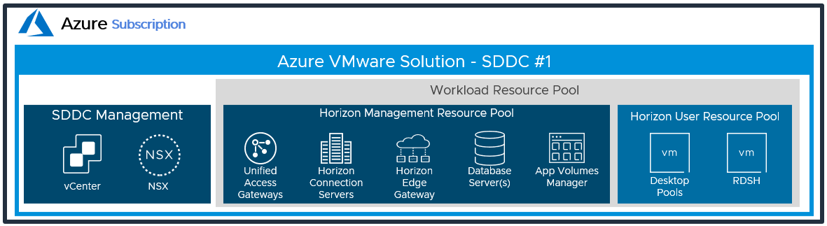
Figure 4: Resource Pools for All-in-SDDC Architecture of Horizon on Azure VMware Solution
Federated Architecture Strategy for Resource Pools
In the federated architecture, only the desktop and RDS resources are located inside the AVS SDDC. There is no need to create sub-resource pools. The Workload resource pool can be used.
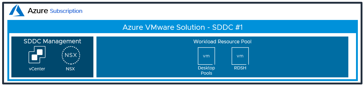
Figure 5: Resource Pools for the Federated Architecture of Horizon on Azure VMware Solution
Scalability and Availability
Like deploying Horizon on-premises, you must size your requirements for deploying Horizon. This section covers the concepts of pods and blocks, Cloud Pod architecture, Horizon Universal Broker, Workspace ONE Access, and Sizing Horizon on Azure VMware Solution.
Block and Pod
A key concept of Horizon, whether deployed on Azure VMware Solution or on-premises is the use of blocks and pods. See the Pod and Block section in Horizon 8 Architecture.
Horizon Universal Broker
The Horizon Universal Broker is a feature of Horizon Cloud Service – first-gen, that allows you to broker desktops and applications to end users across all cloud-connected Horizon pods. For more information, see the Horizon Universal Broker section of the Horizon 8 Architecture chapter, and the Horizon Universal Broker section of the First-Gen Horizon Control Plane Architecture chapter.
Note: At the time of writing, the brokering service from Horizon Cloud Service – next-gen is not supported with Horizon 8 pods and resources.
The Horizon Universal Broker is the cloud-based brokering technology used to manage and allocate Horizon resources from multi-cloud assignments to end users. It allows users to authenticate and access their assignments by connecting to a single fully qualified domain name (FQDN) and then get directed to the individual Horizon pods that will deliver their virtual desktop or published applications. To facilitate user connections to Horizon resources, each Horizon Pod has its own unique external FQDN. See Scaling Deployments.
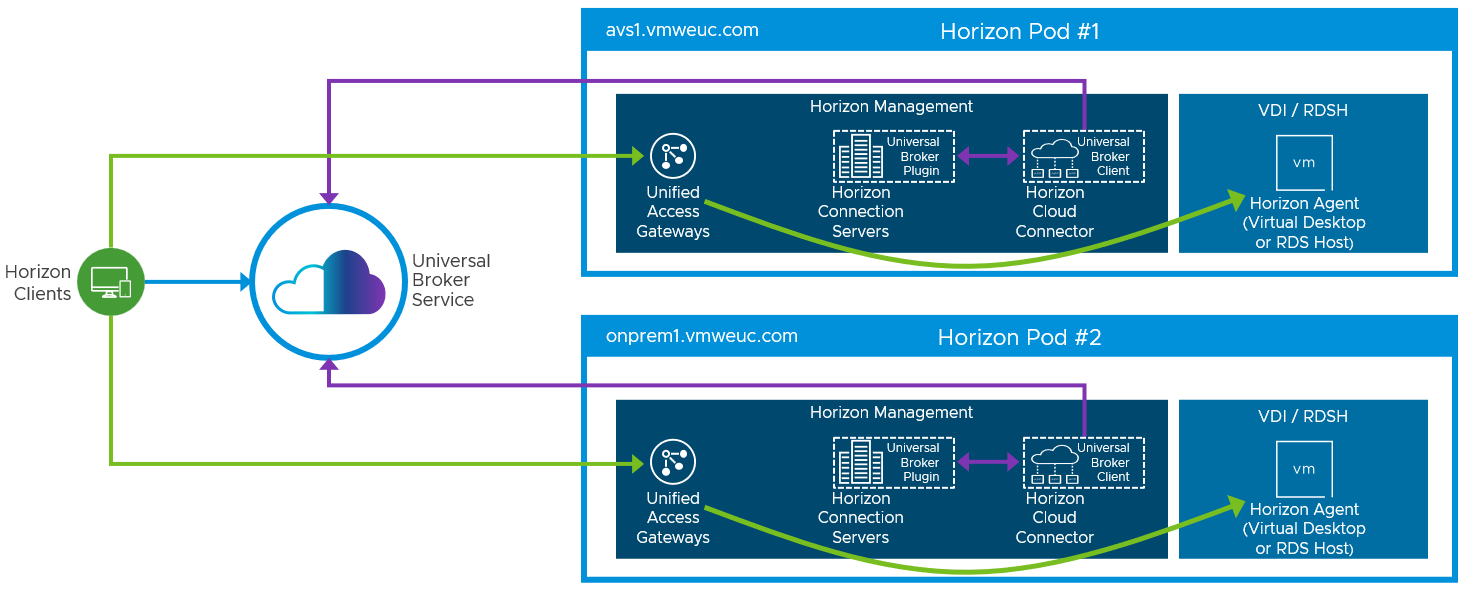
Figure 6: Universal Broker Sample Architecture
Cloud Pod Architecture
As an alternative to Horizon Universal Broker, you can use Cloud Pod Architecture (CPA) to federate multiple Horizon pods either in the same location or across different locations to unite management and user consumption. CPA introduces the concept of a global entitlement (GE) by joining multiple pods together into a federation. This feature allows you to provide users and groups with a global entitlement that can contain desktop pools or RDSH-published applications from multiple different pods that are members of this federation construct.
You can deploy Horizon in a hybrid cloud environment when you use CPA to federate Horizon on-premises pods and Horizon on Azure VMware Solution pods. You can also stretch CPA across two or more Azure VMware Solution data centers. One key consideration when using CPA to be aware of is potential protocol traffic hairpinning of the Horizon session through another Horizon pod and location than where the end user’s resource (desktop or app) is located.
Important: A single pod, and the Connection Servers in it, must be located within a single data center and cannot span locations. Multiple locations must have their own separate pods. These pods can be managed individually or interconnected using Cloud Pod Architecture (CPA).
Note that when using multiple data centers, you must use a storage replication mechanism, such as DFS-R in a hub-spoke topology, for replicating user data.
Of course, the use of CPA is optional. You can choose to deploy Horizon exclusively in a single Azure VMware Solution data center without linking it to any other Horizon pod or you can use Universal Broker.
For more details, see the Cloud Pod Architecture section in Horizon 8 Architecture.
Cloud Pod Architecture for Azure VMware Solution
Cloud Pod Architecture (CPA) is a standard Horizon feature that allows you to connect your Horizon deployment across multiple pods and sites for federated management. It can be used to scale up your deployment, to build a hybrid cloud, and to provide redundancy for business continuity and disaster recovery. CPA introduces the concept of a global entitlement (GE) that spans the federation of multiple Horizon pods and sites. Any users or user groups belonging to the global entitlement are entitled to access virtual desktops and RDS published apps on multiple Horizon pods that are part of the CPA.
Important: CPA is not a stretched deployment; each Horizon pod is distinct and all Connection Servers belonging to each of the individual pods are required to be located in a single location and run on the same broadcast domain from a network perspective.
Here is a logical overview of a basic two-site/two-pod CPA implementation. For Azure VMware Solution, Site 1 and Site 2 might be different AVS Regions, or Site 1 might be on-premises, or another supported cloud provider and Site 2 might be on Azure VMware Solution.

Figure 7: Cloud Pod Architecture
For the full documentation on how to set up and configure CPA, refer to Cloud Pod Architecture in Horizon 8 and the Cloud Pod Architecture section in Horizon Configuration.
Linking Horizon Pods on Azure VMware Solution
You can use the Cloud Pod Architecture feature to connect Horizon pods regardless of whether the pods are on-premises or on Azure VMware Solution. When you deploy two or more Horizon pods on Azure VMware Solution, you can manage them independently or manage them together by linking them with Cloud Pod Architecture.
- On one Connection Server, initialize Cloud Pod Architecture and join the Connection Server to a pod federation.
- After CPA is initialized, you can create a global entitlement across your Horizon pods on-premises and on Azure VMware Solution.
- Optionally, when you use Cloud Pod Architecture, you can deploy a global load balancer (such as Azure Traffic Manager, AVI, or others) between the pods. The global load balancer provides a single-namespace capability that allows the use of a common global namespace when referring to Horizon CPA. Using CPA with a global load balancer provides your end users with a single connection method and desktop icon in their Horizon Client or Workspace ONE console.
Without the global load balancer and the ability to have a single namespace for multiple environments, end users will be presented with a possibly confusing array of desktop icons (corresponding to the number of pods on which desktops have been provisioned for them). For more information on how to set up Cloud Pod Architecture, see the Setting Up Cloud Pod Architecture in Horizon Console.
Use Cloud Pod Architecture to link any number of Horizon pods on Azure VMware Solution. The maximum number of pods must conform to the limits set for pods in Cloud Pod Architecture. See, the VMware Configuration Maximums tool.
When you connect multiple Horizon pods together with Cloud Pod Architecture, the Horizon versions for each of the pods can be different from one another.
Using CPA to Build Hybrid Cloud and Scale for Horizon
You can deploy Horizon in a hybrid cloud environment when you use CPA to interconnect Horizon on-premises and Horizon pods on Azure VMware Solution. You can easily entitle your users to virtual desktop and RDS published apps on-premises and/or on Azure VMware Solution. You can configure it such that they can connect to whichever site is closest to them geographically as they roam.
You can also stretch CPA across Horizon pods in two or more Azure VMware Solution regions with the same flexibility to entitle your users to one or multiple pods as required.
Using CPA to Provide BC and DR for Horizon
Unlike traditional BCDR (business continuity and disaster recovery) solutions for apps, where replication of all data from the primary site to the secondary site is needed, we recommend a different approach for Horizon, using CPA. Because the majority of VDI and RDS deployments use non-persistent and stateless virtual machines that can be created and recreated very quickly, it is senseless to replicate them across sites. CPA can be used across on-premises Horizon pods (primary site) and Horizon pods on Azure VMware Solution (secondary site) for the purpose of BCDR. By using Azure VMware Solution as a secondary site for BCDR, you can take advantage of the hourly billing option and the pay-as-you-go benefit.
During normal operations, keep a small host footprint on Azure VMware Solution where you will deploy your Horizon instance, store your updated golden images, and create a small pool of VMs. Note that there is a minimum number of hosts requirement per SDDC. When the primary site goes down, you can simply create new virtual desktops as well as new hosts on the secondary site from the very same golden image. Use Global Entitlements to ensure that your end users can access desktops on the secondary site.
You must keep persistent data such as user profiles, user data, and golden images synced between the two sites by using a storage replication mechanism, such as DFS-R in a hub-spoke topology or another third-party file share technology. If you also use App Volumes and Dynamic Environment Manager, then Packages and file share data will also need to be replicated from the primary site to the secondary site.
An important consideration in leveraging Azure VMware Solution as a secondary site for BCDR involves host availability at the AVS data center when you need your BCDR capacity. Although there might be hosts available that can be used to expand your secondary site, depending on your RTO (Recovery Point Objective) and growth requirement, you might not be able to reach your target number right away. The only way to guarantee the number of hosts you need right away is to reserve them ahead of time, but the tradeoff is the high cost. There are things you can do to optimize your availability and cost:
- Segment end-user populations into tiers in terms of RTO (recovery time objective). Some user segments might require a secondary desktop right away. You should have desktops created and on standby for them.
- Other user segments might be able to tolerate longer RTO and might require a secondary desktop within hours rather than minutes. In this case, you can wait for new hosts and desktops to be created.
- Each new host takes time to create, assuming the data center has an available physical server.
Work with your Microsoft sales representative to ensure that you will have adequate BCDR capacity when you need it.
BC and DR for Horizon Full-Clone Desktops
The BCDR (business continuity and disaster recovery) workflow recommended in the previous section works well for non-persistent instant clones. There are some additional considerations for the protection of persistent full-clone desktops.
First, consider whether your users require mirror image desktops after a primary site failure? If the answer is yes, you must replicate your primary full-clone desktops periodically to the secondary site. This is the most expensive type of protection for every primary full-clone desktop; you will need an equivalent secondary full-clone desktop on Azure VMware Solution, always running. You must also script the import of secondary desktops into the Connection Servers on the secondary site as a manual full-clone pool.
Most customers find that, given the cost of providing a fully mirrored desktop, it is acceptable to give their persistent full-clone desktop users a secondary desktop that is a pristine copy of the same golden image. Any user customization or data not saved in a file share and replicated to the secondary site will be lost, so you must ensure that all important user data resides on a file share. You can then use the sample workflow in the previous section (Using CPA to Provide BC and DR for Horizon) to provision either an instant-clone desktop or a full-clone desktop on the secondary site for BCDR purposes.
Workspace ONE Access
Workspace ONE® Access can be used to broker Horizon resources. In this case, the entitlements and resources are synched to Workspace ONE Access, and Workspace ONE Access knows the FQDN of each Horizon Pod to properly direct users to their desktop or application resources. Workspace ONE Access can also be used in combination with Universal Broker with Multi-Cloud Assignments or with Cloud Pod Architecture and Global Entitlements.
For more design details, see Horizon and Workspace ONE Access Integration in the Platform Integration chapter.
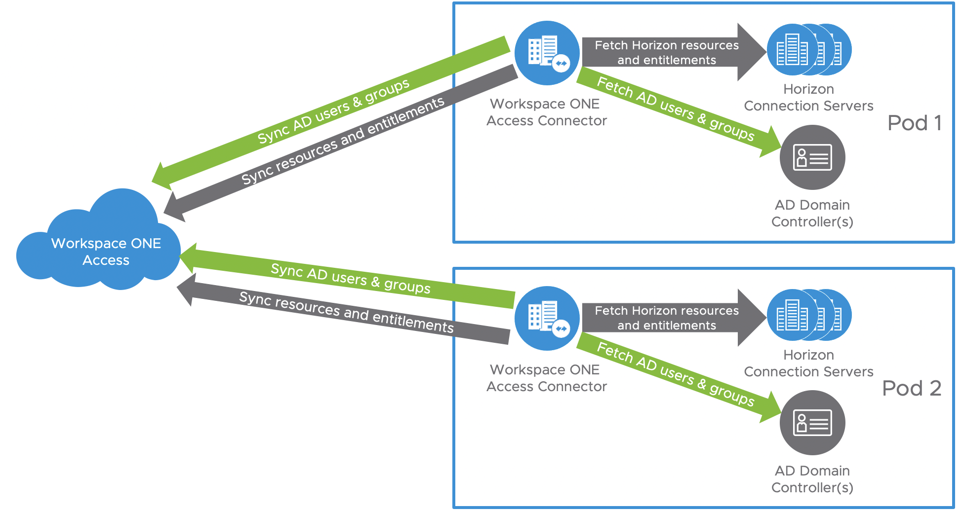
Figure 8: Syncing Horizon Resources into Workspace ONE Access
AVS SDDC Sizing
The overall methodology for sizing Horizon on Azure VMware Solution is the same as for on-premises deployments. You must size your requirements for deploying Horizon on Azure VMware Solution to determine the number of hosts you must deploy for the following purposes:
- Your virtual desktop or RDS workloads.
- SDDC infrastructure components on Azure VMware Solution. These components are deployed and managed automatically for you by Microsoft, but you will require capacity in your SDDC.
At the time of this update, the minimum number of hosts required per SDDC on Azure VMware Solution for production use is 3 nodes (hosts). See Hosts for the RAM, CPU, and disk capacities of the hardware in Azure VMware Solution.
One design consideration in sizing an SDDC is the throughput capability of the SDDC networking and the NSX edge gateways. Each user session will generate a certain amount of traffic that needs to pass through the NSX edge gateways.
Each SDDC can handle up to 4,000 desktop or application sessions, assuming:
- The workload traffic aligns with the LoginVSI task worker profile.
- Only protocol traffic is considered, no user data.
- NSX Edge gateways are configured to be large.
Your workload profile and needs may be different, and therefore results may vary based on your use case. User data volumes may lower scale limits in the context of your workload. Size and plan your deployment accordingly. Work with your VMware team to help determine the correct sizing.
Network Configuration
This section covers the network configurations when deploying Horizon on Azure VMware Solution.
All-In-SDDC Architecture Networking
When the All-in-SDDC Architecture is used, all the networking for the Horizon Management components is done within NSX-T inside the AVS SDDC.
The recommended network architecture consists of a double DMZ and a separation between the Unified Access Gateway appliances and the RDS and VDI virtual machines located inside the SDDC. You must create segments in NSX-T to use within your SDDC. You will need the segments listed below. Review the NSX-T documentation for details.
- NSX-T Desktop / RDS Segments with DHCP Enabled
- NSX-T Management Segment (DHCP Optional)
- Connection Servers
- Unified Access Gateway - Deployed as two-NIC
- App Volumes Managers
- File Server
- Database Server
- Workspace ONE Connector
- Horizon Edge Gateway Appliance (used when connecting to Horizon Cloud Service – next-gen)
- Horizon Cloud Connector Appliance (used when connecting to Horizon Cloud Service – first-gen)
- NSX-T Segment for Unified Access Gateway Internal DMZ
- NIC 2 on each Unified Access Gateway
- NSX-T Segment for Unified Access Gateway External DMZ
- NIC 1 on each Unified Access Gateway
The following diagram illustrates this networking configuration.
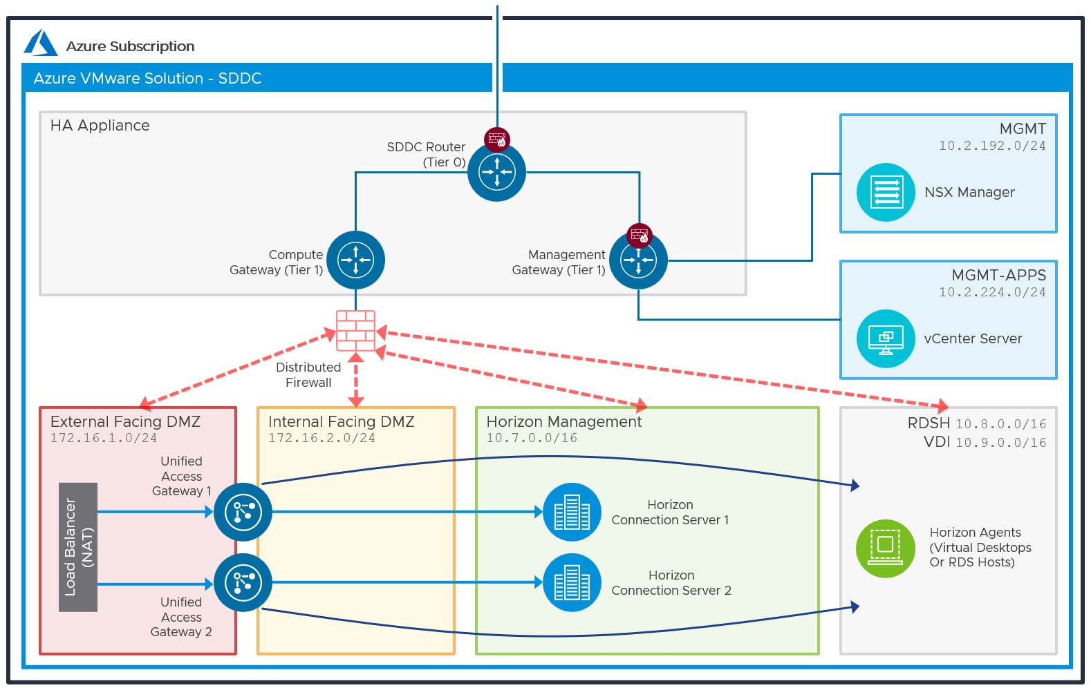
Figure 9: Network Diagram with All-In-SDDC Architecture (Subnets are for Illustrative Purposes Only)
External Access to All-in-SDDC Deployments
To provide external user access to desktops and apps, inbound network traffic must be routed through Azure into the SDDC.
There are different options for providing inbound traffic in Azure including:
- Azure Application Gateway with L7, Secure Sockets Layer (SSL) termination, and Web Application Firewall.
- DNAT and load balancer from on-premises.
- Azure Virtual Network, NVA, and Azure Route Server in various scenarios.
- Virtual WAN secured hub with Azure Firewall, with L4 and DNAT.
- Virtual WAN secured hub with NVA in various scenarios.
See Example architectures for Azure VMware Solutions for more information.
Regardless of the method used to provide inbound Internet access, you should ensure that this allows the required Horizon network ports to be routed to the appropriate components inside the SDDC. See Network Ports in VMware Horizon for more information on the ports and their function.
Federated Architecture Networking
In the Federated Architecture, all of the Horizon management components including the Unified Access Gateway appliances are located inside Azure. This allows the use of multiple AVS SDDCs as a target for capacity for desktops / RDS hosts. In the Federated Architecture, you will need to create a subnet for the Horizon Management components in a VNet.
- NSX-T - Desktop / RDS Segments with DHCP Enabled
- Subnet in Azure VNet for Horizon Management Components
- Connection Servers
- Unified Access Gateway - Deployed as two-NIC
- App Volumes Managers
- File Server
- Database Server
- Workspace ONE Connector
- Horizon Cloud Connector
- New VNet subnet for Internal DMZ
- New VNet subnet for External DMZ
The following diagram illustrates the network design of the Federated Architecture.
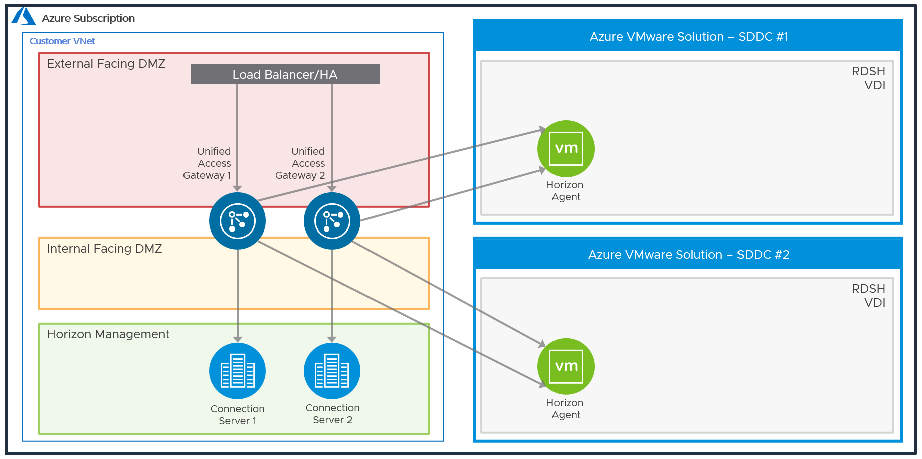
Figure 10: Network Diagram with Federated Architecture (Subnets are for Illustrative Purposes Only)
The Unified Access Gateways are deployed in a dual NIC configuration, each NIC residing in a different DMZ, acting as a gatekeeper between them. Only after authentication is successful, access to anything beyond the login page is allowed.
External Access to Federated Deployments
When direct external access for virtual desktops and published apps is required, configure a public IP address with Network Address Translation towards the virtual IP address of the load balancer used for the Unified Access Gateways. A DNS host entry should also be created for the public IP address.
Load Balancing Unified Access Gateway Appliances
To ensure redundancy and scale, multiple Unified Access Gateways (UAGs) are deployed. A minimum of two Unified Access gateways should be deployed in a two-NIC (Double DMZ) configuration. See Two-NIC Deployment in the Unified Access Gateway Architecture chapter for details.
To implement them in a highly available configuration, provide a virtual IP address (VIP), and present users with a single namespace, the following options can be used.
- A third-party load balancer, such as the Azure Load Balancer or the NSX Advanced Load Balancer (Avi) can be used.
- Unified Access Gateway high availability (HA) can be used. See the high availability section of the Unified Access Gateway Architecture chapter for more information.
See Load Balancing Unified Access Gateway in Horizon 8 Architecture for details on load-balancing the UAG appliances.
To provide direct external access, a public IP address would be configured that forwards traffic to the load balancer virtual IP address. An external DNS host record for that IP address should also be created.
When using UAG high availability, n+1 public IP addresses are required:
- One IP address for the load-balanced floating virtual IP address (VIP) used for the XML-API
- An additional one per Unified Access Gateway appliance for the secondary Horizon protocol traffic (Blast, PCoIP, tunnel)
Table 1: Unified Access Gateway Deployment Strategy
| Decision | Unified Access Gateways are deployed in an N+1 model. |
| Justification | Multiple Unified Access Gateways allow for scale and redundancy. |
All-in-SDDC Deployment of Unified Access Gateways
In the All-in-SDDC Architecture, the Unified Access Gateway appliances are located inside of the AVS SDDC. There are different options for balancing traffic between multiple Unified Access Gateways (UAGs) and providing redundancy:
- With a third-party load balancer deployed into the SDDC
- Using UAG high availability (HA)
- Using an Azure load balancer service
In this configuration, internal and external DMZ segments should be created in AVS with the following firewall rules:
- Internal-DMZ – Access to network segments containing desktops, connection servers, and DNS
- External-DMZ – Access to the network segment containing the third-party load balancer or UAG VIP
Static routes might be needed on the Unified Access Gateway as follows:
- Internal-DMZ (NIC 2) – Static route to network segments containing desktops and the connection servers
- External-DMZ (NIC 1) – Static route to network segments containing the third-party load balancer (if this is located in a different network segment)
Table 2: Load Balancing Strategy for All-in-SDDC Architecture
| Decision | Unified Access Gateway high availability was used. |
| Justification | This allows a multiple UAGs to be deployed and present a single namespace. Sessions can be balanced across the UAG appliances, allowing for scale and redundancy. UAG HA is easy to implement and does not require an additional load balancer. |
Federated Deployment of Unified Access Gateways
In this Architecture, the UAG appliances are located directly in Azure, which eliminates the need to place a third-party load balancer to forward protocol traffic into the SDDC. It also prevents protocol hairpinning when using cloud-pod inside of Azure. See the Deploying Unified Access Gateway on Microsoft Azure for details on the deployment of UAG into Azure.
In this configuration, Internal and External DMZ VNet subnets should be created in Azure with the following VNet Peering and firewall rules:
- Internal DMZ – Access to segments (VNet Peering) containing desktops, connection servers, and DNS.
- External DMZ – Access to the third-party load balancer (if used). If using the built-in Azure load balancer, this VNet network needs no peering configured.
Static routes might be needed on the Unified Access Gateway as follows:
- Internal DMZ (NIC 2) – Static route to segments containing desktops and the connection servers.
See Change Network Settings for details on setting static routes in Unified Access Gateway.
Table 3: Load Balancing Strategy for Federated Architecture
| Decision | A third-party load balancer was used to load balance the Unified Access Gateways. The Azure Load Balancer was used. |
| Justification | A load balancer enables the deployment of multiple management components, such as Unified Access Gateways, to allow scale and redundancy. The Azure load balancer can load balance the Unified Access Gateway appliances in Azure. |
Load Balancing Connection Servers
Multiple Horizon Connection Servers are deployed for scale and redundancy.
Depending on the user connectivity, you may or may not need to deploy a third-party load balancer to provide a single namespace for the Connection Servers. When all user connections originate externally and come through a Unified Access Gateway, it is not necessary to have a load balancer for the Connection Servers. Each Unified Access Gateway can be defined with a specific Connection server as its destination.
Although the following diagram shows a 1-to-1 mapping of Unified Access Gateway to Connection Server, it is also possible to have an N-to-1 mapping, where more than one Unified Access Gateway maps to the same Connection Server.
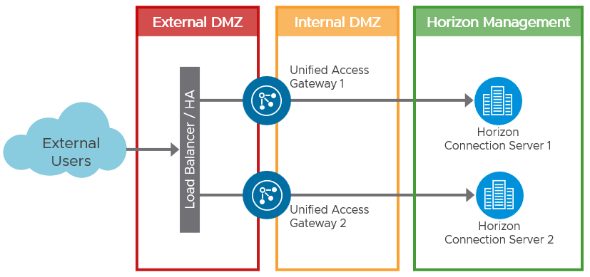
Figure 11: Load Balancing when all Connections Originate Externally
Where users will be connecting from internally routed networks and their session will not go via a Unified Access Gateway, a load balancer should be used to present a single namespace for the Connection Servers to the users. A load balancer such as the Azure Load Balancer or NSX Advanced Load Balancer (Avi), can be deployed. See the Load Balancing Connection Servers section of the Horizon 8 Architecture chapter.
When required for internally routed connections, a load balancer for the Connection Servers can be either:
- Located so that only the internal users use it as an FQDN.
- Placed in between the Unified Access Gateways and the Connection Server and used as an FQDN target for both internal users and the Unified Access Gateways.
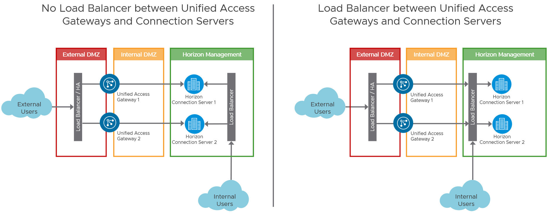
Figure 12: Options for Load Balancing Connection Servers for Internal Connections
Table 4: Load Balancing Connection Servers Strategy
| Decision | No load balancer was used for the Connection Servers. |
| Justification | All the users will connect to the environment externally through the Unified Access Gateways. |
External Networking
For external management or access to external resources, create an ExpressRoute to the tier 0 router.
Azure Express Route is a cloud service solution that makes it easy to establish a dedicated network connection from your on-premises to Azure. Using ExpressRoute, you can establish private connectivity between Azure and your data center, office, or co-location environment, which in many cases can reduce your network costs, increase bandwidth throughput, and provide a more consistent network experience than Internet-based connections.
Azure ExpressRoute lets you establish a dedicated network connection between your network and one of the connectivity provider locations. Using industry-standard 802.1q VLANs, this dedicated connection can be partitioned into multiple virtual interfaces.
Networking to On-Premises
If you already have an on-premises environment, you can scale out this environment by adding one or more SDDCs on Azure VMware Solution and forming a new Horizon Pod.
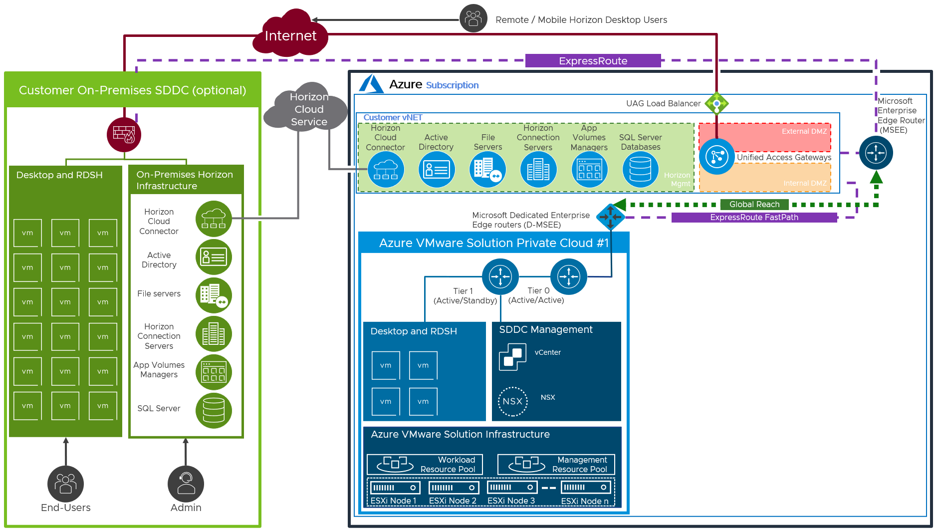
Figure 13: Networking to On-Premises (Federated Architecture shown)
Azure ExpressRoutes with Fast Path are used between on-premises (or Exchange provider facility), customer vNet, and Azure VMware Solution (SDDC). See Configuring Azure ExpressRoute, for more detail. Global Reach is also required for routing between ExpressRoute circuits, like on-premises towards SDDCs or between SDDCs. See about ExpressRoute Global Reach for more detail.
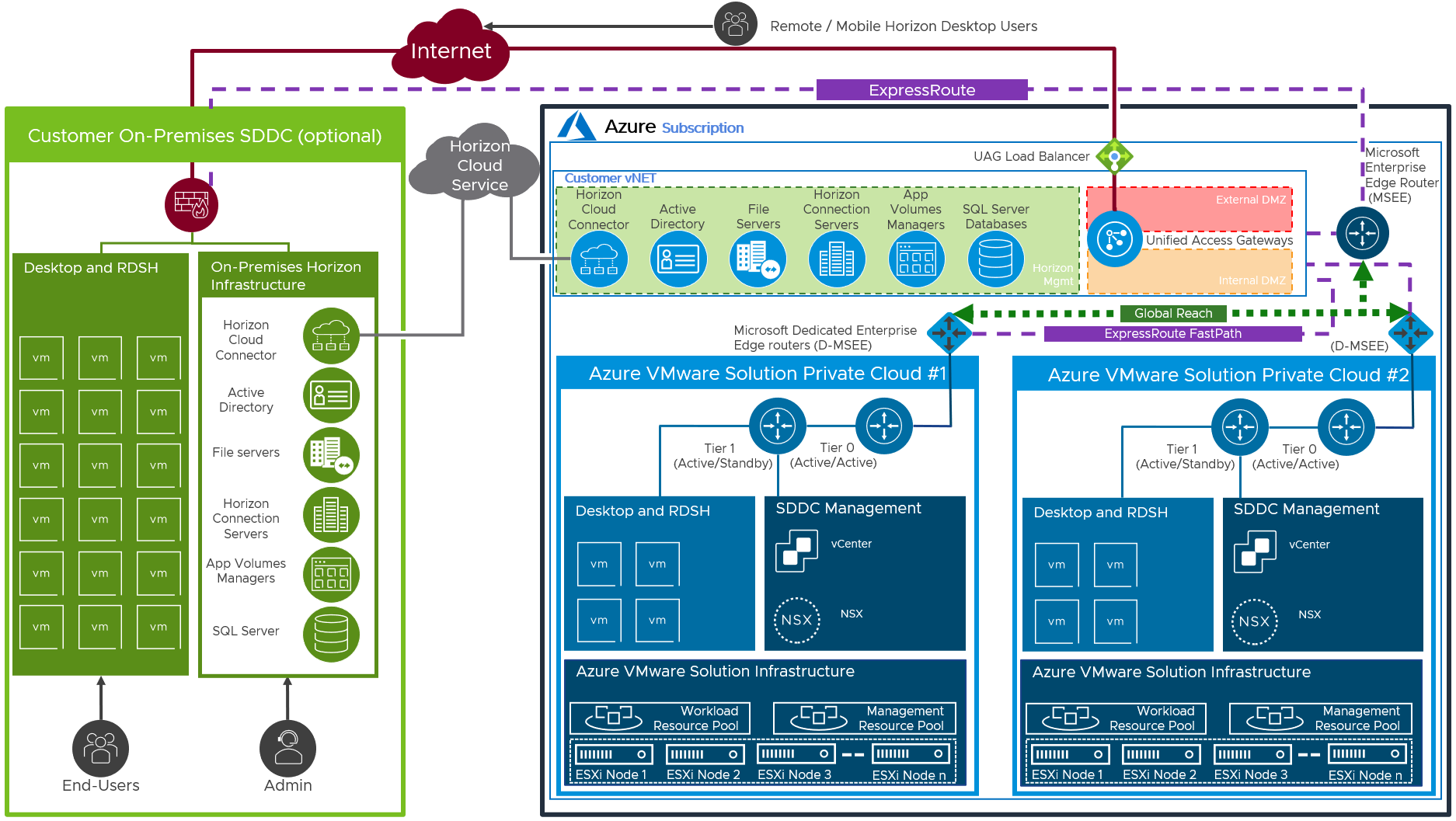
Figure 14: Azure ExpressRoute between Azure and On-Premises Locations (Federated Shown)
From on-premises or between Azure VNet Horizon pods, Active Directory, fileservers, and Horizon Cloud Pod Architecture are replicated. In this reference architecture, separate FQDNs were used per site, but when a single FQDN is used the Unified Access Gateways need protocol connectivity to the desktop’s subnets in a many-to-many configuration.
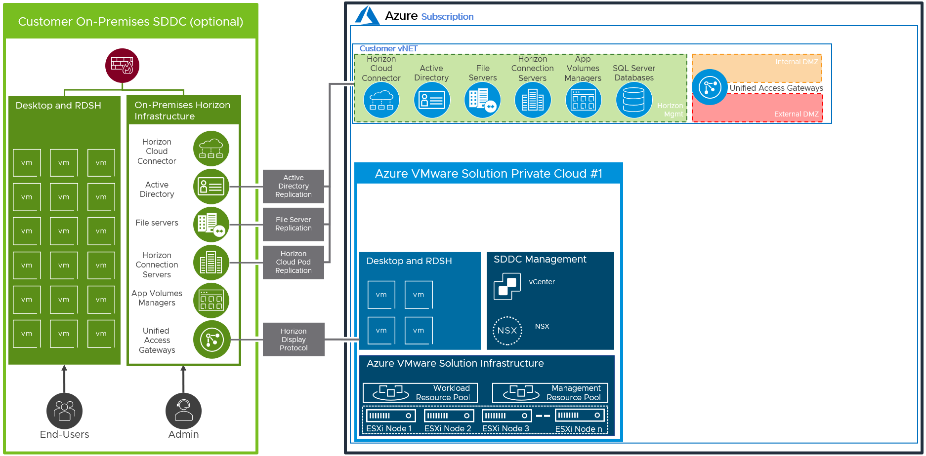
Figure 15: Replication between Horizon Azure VMware Solution and On-Premises Deployments (Federated Shown)
Table 5: Networking to On-Premises
| Decision | Networking was configured to an on-premises location. |
| Justification | This allows data, such as file shares and active directory, to be replicated between the Horizon deployment in Azure VMware Solution and an on-premises Horizon deployment. |
Data Egress Cost
Unlike on-premises deployments, deploying Horizon on Azure VMware Solution incurs data egress costs based on the amount of data egress traffic the environment will generate. It is important to understand and estimate the data egress traffic.
Understanding Different Types Data Egress Traffic
Depending on the deployment use case, you might be incurring costs for some or all of the following types of data egress traffic:
- End-user traffic via the Internet – You have configured your environment where your end users will connect to their virtual desktops on Azure VMware Solution remotely via the Internet. Any data leaving the Azure VMware Solution data center will incur egress charges. Egress data consists of the following components: outbound data from Horizon protocols and outbound data from remote experience features (for example, remote printing). Although the former is typically predictable, the latter has more variance and depends on the exact activity of the user.
- End-user traffic via the on-premises data center – You have configured your environment where your end users will connect to their virtual desktops on Azure VMware Solution via your on-premises data center. In this case, you will have to link your data center with the Azure VMware Solution data center using ExpressRoute. Any data traffic leaving the Azure VMware Solution data center and traveling back to your data center will incur egress charges. And if you have Cloud Pod Architecture (CPA) configured between the on-premises environment and the Azure VMware Solution environment, you will incur egress charges for any CPA traffic between the two pods (although CPA traffic is typically fairly light).
- External application traffic – You have configured your environment where your virtual desktops on Azure VMware Solution must access applications hosted either in your on-premises environment or in another cloud. Any data traffic leaving the Azure VMware Solution data center and traveling to these other data centers will incur egress charges.
Note: Data traffic within your Azure VMware Solution organization or between the organization and Azure services in that same region is exempt from egress charges. However, any traffic from the organization to another availability zone or to another AVS region will be subject to egress charges.
Data ingress (that is, data flowing into the Azure VMware Solution data center) is free of charge.
Estimating Data Egress Traffic
Because the data egress cost is priced per GB, the best way to estimate your data egress cost is to estimate your likely data egress traffic by using a monitoring tool in your existing on-premises environment (whether it is already virtualized or not). Make sure you estimate the different types of data egress traffic listed previously separately as applicable.
Scaling Deployments
In this section, we will discuss options for scaling out Horizon on Azure VMware Solution. Following are the design decisions for both the All-in-SDDC and the Federated architectures.
All-in-SDDC - Single SDDC
This design is comprised of a single SDDC which will handle up to approximately 4,000 concurrent Horizon users. There will be a single FQDN (desktops.customer.com) bound to the Public IP address. A third-party load balancer is used to forward Horizon protocol traffic to the UAG appliances located inside of the SDDC.
Users will use the desktops.customer.com FQDN via the Horizon Client, HTML access, or it will automatically be used when integrated with Workspace ONE Access. The following figure is a logical view of the All-in-SDDC Architecture showing all the Horizon components (Management and User Resources) located inside of the SDDC.
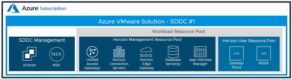
Figure 16: Logical Architecture for a single SDDC with the All-in-SDDC Architecture
The following figure illustrates the collection flow with a single SDDC using the All-in-SDDC Architecture. 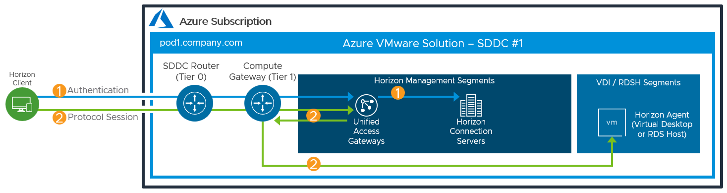
Figure 17: Horizon Connection Flow with Single SDDC using the All-in-SDDC Architecture
The figure below shows the All-in-SDDC Architecture, with all networking done via NSX-T inside the SDDC.
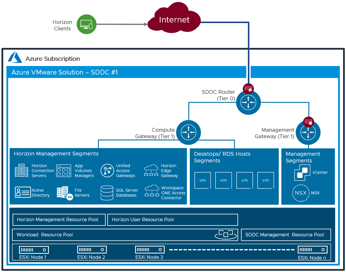
Figure 18: All-in-SDDC Architecture with a Single SDDC with Networking
Table 6: Connection Server Strategy for the All-in-SDDC Architecture
| Decision | Two connection servers were deployed. These ran on dedicated Windows Server VMs located in the internal network segment within the SDDC. |
| Justification | One Connection Server supports a maximum of 4,000 sessions. A second server provides redundancy and availability (n+1). |
Table 7: Unified Access Gateway Strategy for the All-in-SDDC Architecture
| Decision | Two standard-size Unified Access Gateway appliances were deployed inside the AVS SDDC as part of the Horizon All-in-SDDC Architecture. These spanned the Internal and External DMZ network segments. Unified Access Gateway high availability (HA) was used. |
| Justification | UAG provides secure external access to internally hosted Horizon desktops and applications. One standard UAG appliance is recommended for up to 2,000 concurrent Horizon connections. A second UAG provides redundancy and availability (n+1). UAG high availability presents and single namespace, balances sessions across the appliances, and supports scale and redundancy. |
Table 8: App Volumes Manager Strategy for the All-in-SDDC Architecture
| Decision | Two App Volumes Managers were deployed. The two App Volumes Managers are load balanced with the NSX Advanced load balancer. |
| Justification | App Volumes is used to deploy applications locally. The two App Volumes Managers provide scale and redundancy. |
Table 9: Horizon Edge Gateway Strategy for the All-in-SDDC Architecture
| Decision | A Horizon Edge Gateway was deployed in the internal network. One per Horizon pod. |
| Justification | The Horizon pod needs to connect to the Horizon Cloud Service to enable the use of subscription licensing. The Horizon Edge Gateway connects to the Horizon Cloud Service – next-gen.. |
Table 10: Dynamic Environment Manager Strategy for the All-in-SDDC Architecture
| Decision | VMware Dynamic Environment Manager™ (DEM) was deployed on local file servers. |
| Justification | This is used to provide customization/configuration of the Horizon desktops. This location contains the Configuration and local Profile shares for DEM. |
Table 11: SQL Server Strategy for the All-in-SDDC Architecture
| Decision | A single SQL server was deployed. |
| Justification | This SQL server was used for the Horizon Events Database and App Volumes. |
Table 12: Load balancing strategy for the All-in-SDDC Architecture
| Decision | A third-party load balancer was used to load balance the Unified Access Gateways and App Volumes Managers. NSX Advanced load balancer was used. |
| Justification | A load balancer enables the deployment of multiple management components, such as Unified Access Gateways, to allow scale and redundancy. |
All-in-SDDC - Multiple SDDCs
As the All-in-SDDC architecture for Horizon in Azure VMware Solution places all the management components inside each SDDC, there are some considerations when scaling above a single SDDC.
- Each SDDC hosts a separate Horizon pod each with their own set of Horizon Connection Servers.
- Each pod requires a separate FQDN and can be addressed separately.
- Cloud Pod Architecture is not supported with the All-in-SDDC Architecture.
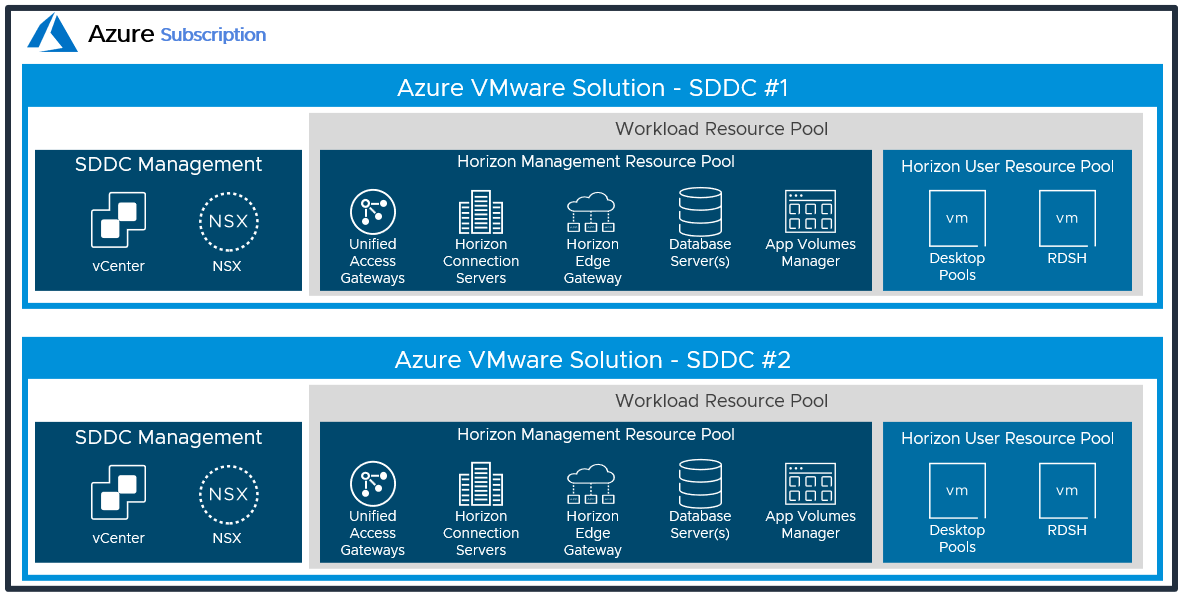
Figure 19: Logical Architecture for the All-in-SDDC Architecture with Multiple SDDCs
With the All-in-SDDC Architecture, the key recommendation is that a Horizon pod should only contain a single Azure VMware Solution SDDC. As mentioned earlier, each pod will have a dedicated FQDN for user access. For example, pod1.company.com and pod2.company.com. Each pod/SDDC would have a dedicated external IP address that would tie to its FQDN.
As illustrated in the figure below, users’ sessions would be directed to a particular Horizon pod and therefore the SDDC that hosts that pod. This avoids the possibility of protocol traffic hairpinning through one SDDC to get to the destination SDDC.
Universal Broker can be used to provide a single FQDN for user logon. This would then direct the user’s session to the correct individual Horizon pod’s FQDN where their chosen resources are located. Alternatively, users could just directly connect to individual pods using the Horizon Client, although that requires the user to choose the correct pod for the desired resource.
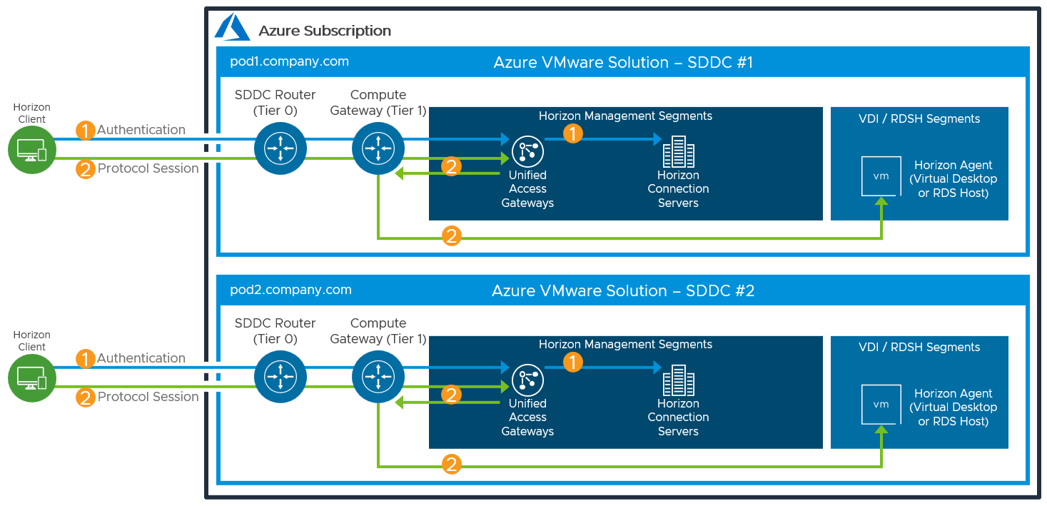
Figure 20: Horizon connection flow for All-in-SDDC Architecture with Multiple SDDCs
Just like in the single All-in-SDDC design, all of the Horizon components are located inside each SDDC.
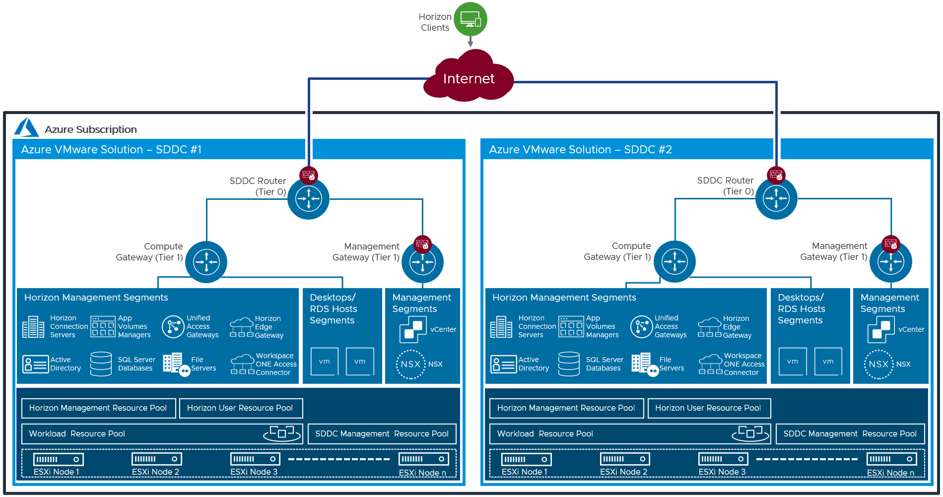
Figure 21: All-in-SDDC Architecture with two SDDCs and Networking
Federated - Single SDDC
In the Federated Architecture, all the Horizon Management components are located inside of native Azure. There is a still guidance of approximately 4,000 concurrent connections per SDDC, but the federated architecture allows you to create a Horizon pod consisting of multiple SDDCs. This solution is architected the same way that on-premises Horizon is architected, and the front-end management components would just need to be scaled to handle the concurrent connections from the back end AVS desktop resources. This allows easier future scaling of capacity through the addition of more SDDCs to the pod, without having to relocate the management components.
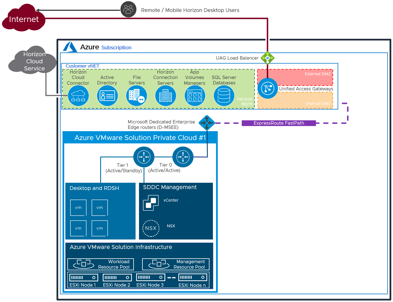
Figure 22: Logical Architecture of a Federated Deployment using a Single SDDC
Table 13: Federated Deployment Strategy
| Decision | A single SDDC was deployed in Azure VMware Solution. The Horizon management servers were located in Azure. |
| Justification | Locating the management servers in Azure allows the Horizon pod to scale beyond the limits of a single SDDC. |
Table 14: Connection Server Strategy for Federated Deployment
| Decision | Two Horizon Connection Servers were deployed. These ran on dedicated Windows Server VMs, located in the Azure vNet. |
| Justification | One Connection Server supports a maximum of 4,000 sessions. A second server provides redundancy and availability (n+1). |
Table 15: Unified Access Gateway Strategy for Federated Deployment
| Decision | Two standard-size Unified Access Gateway appliances were deployed. These were located in the Azure DMZ network. |
| Justification | UAG provides secure external access to internally hosted Horizon desktops and applications. One standard UAG appliance is recommended for up to 2,000 concurrent Horizon connections. A second UAG provides redundancy and availability (n+1). |
Table 16: App Volumes Manager Strategy for Federated Deployment
| Decision | Two App Volumes Managers were deployed, located in the Azure vNet. The two App Volumes Managers are load balanced with a third-party load balancer. |
| Justification | App Volumes is used to deliver applications to the virtual desktops and RDS Hosts. Two App Volumes Managers provide scale and redundancy and meet the target scale of the environment. |
Table 17: Horizon Cloud Connector Strategy for Federated Deployment
| Decision | One Horizon Cloud Connector was deployed and located in the Azure vNet. |
| Justification | The Horizon Cloud Connector is required to license Horizon with subscription licensing. |
Table 18: Workspace ONE Access Connector Strategy for Federated Deployment
| Decision | One Workspace ONE Access Connector was deployed into the Azure vNet |
| Justification | The connector enables the synchronization of Horizon entitlements into Workspace ONE Access. The use of Workspace ONE Access allows for seamless brokering into desktops and applications. Locating a connector locally in Azure ensures that resource synchronization does not rely on connectors in other locations and any dependency they may include. |
Table 19: Dynamic Environment Manager Strategy for Federated Deployment
| Decision | Dynamic Environment Manager (DEM) was deployed on the File Server. |
| Justification | DEM provides configuration and personalization of the users’ Horizon desktops and published applications. Locating a file server for DEM data in Azure brings this data locally to the Horizon desktops and published applications and reduces latency. |
Table 20: SQL Server Strategy for Federated Deployment
| Decision | A SQL server was deployed. |
| Justification | The SQL server was used for the Horizon Events database and the App Volumes database. |
Federated – Multiple SDDC
An existing Horizon Pod based on AVS can be extended with multiple SDDCs to scale the pod out.
Each SDDC uses an ExpressRoute with a FastPath circuit to connect the SDDC to the vNet. A connection to an on-premises or co-location site also uses an ExpressRoute circuit. Currently, you can link a single virtual network (vNet) with up to four ExpressRoute circuits in either the same or different peering locations. See ExpressRoute FAQ.
You can extend beyond a single Horizon Pod by creating separate Horizon Pods in new Azure vNets. The vNets and Horizon Pods can be in the same Azure region or in different Azure regions.
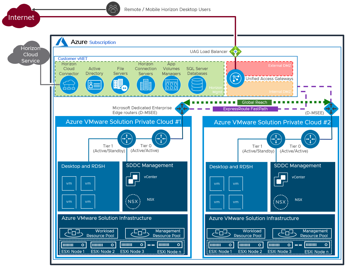
Figure 23: Logical Architecture of a Federated Deployment using Multiple SDDC
Protocol Traffic Hairpinning
One consideration to be aware of is the potential hairpinning of the Horizon protocol traffic through another Horizon pod or SDDC than the one where the user Horizon resource is located. This can occur if the user’s session is initially sent to the wrong SDDC for authentication. With each SDDC, all traffic into and out of the SDDC goes via the NSX edge gateways and there is a limit to the traffic throughput. In the All-in-SDDC architecture, the management components, including the Unified Access Gateways, are located inside the SDDC, authentication traffic must enter an SDDC and pass through the NSX edge gateway.
If the authentication traffic is not precisely directed, by using a unique namespace for each Horizon Pod, the user could be directed to any Horizon pod in its respective SDDC. If the user’s Horizon resource is not in that SDDC where they are initially directed to for authentication, their Horizon protocol traffic would go into the initial SDDC to a Unified Access Gateway in that SDDC and then back out via the NSX edge gateways and then be directed to where their desktop or published application is being delivered from.
This causes a reduction in achievable scale due to this protocol hairpinning. For this reason, Cloud Pod Architecture is not supported in the All-In-SDDC Architecture and caution should be exercised if using Horizon Cloud Pod Architecture in the Federated Design. If you create a Cloud Pod Federation that contains both a Horizon pod on-premises and a Horizon pod in AVS, you could run into a similar issue where the user gets directed to one pod which does not contain their assigned resource and then would be routed back out to the other pod. This flow is illustrated in the following diagram.
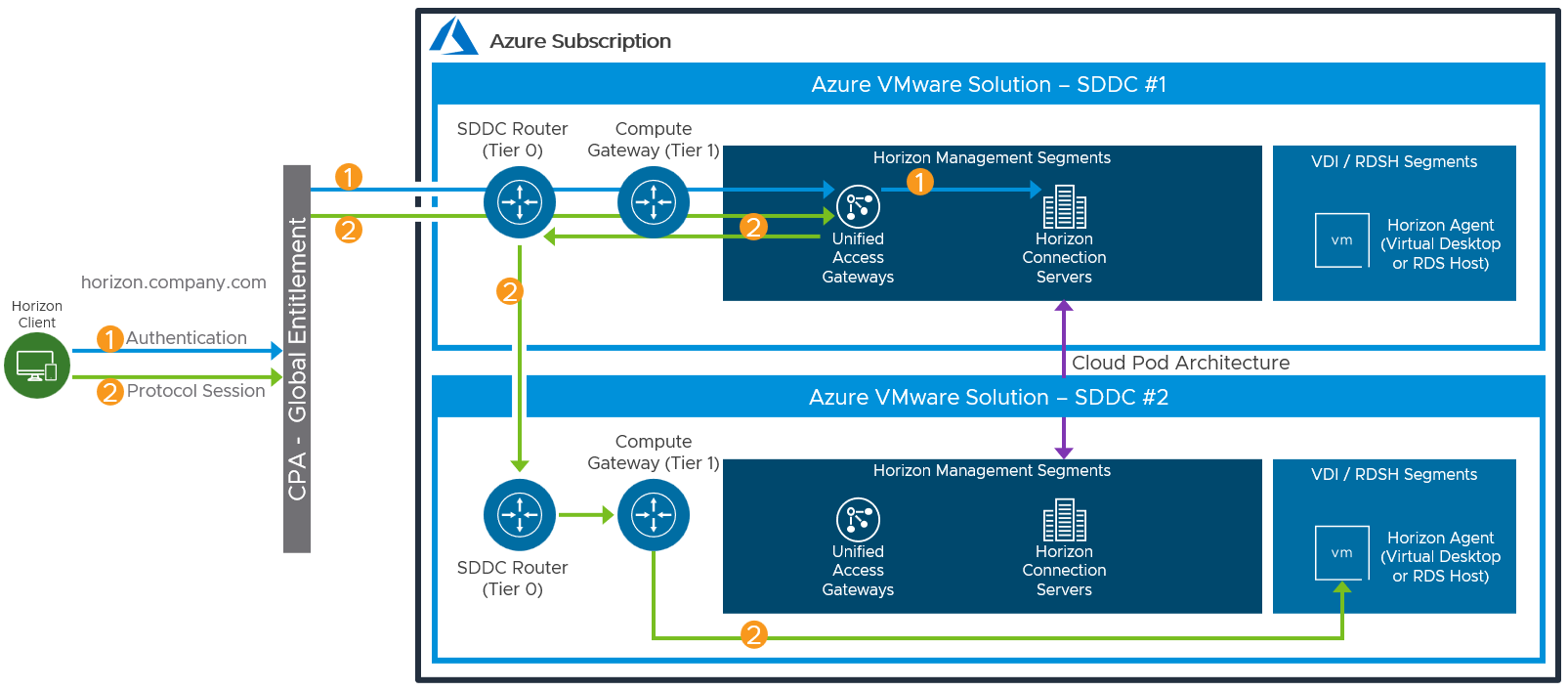
Figure 24: Potential Horizon Protocol Traffic Hairpinning
Licensing
To enable the use of subscription licensing, each Horizon pod must be connected to the Horizon Cloud Service. For more information on how to do this, see the Horizon Cloud Service section of the Horizon 8 Architecture chapter.
For a POC or pilot deployment of Horizon on Azure VMware Solution you may use a temporary evaluation license or your existing perpetual license. However, to enable Horizon for production deployment on Azure VMware Solution, you must purchase a Horizon subscription license. For more information on the features and packaging of Horizon subscription licenses, see VMware Horizon Subscription - Feature comparison.
You can use different licenses on different Horizon pods, regardless of whether the pods are connected by CPA. You cannot mix different licenses within a pod because each pod only takes one type of license. For example, you cannot use both the Horizon Apps Universal Subscription license and the Horizon Universal Subscription license in a single pod.
Preparing Active Directory
Horizon requires Active Directory services. For supported Active Directory Domain Services (AD DS) domain functional levels, see the VMware Knowledge Base (KB) article Supported Operating Systems, Microsoft Active Directory Domain Functional Levels, and Event Databases for VMware Horizon 8 (78652).
If you are deploying Horizon in a hybrid cloud environment by linking an on-premises environment with an Azure VMware Solution Horizon pod, you should extend the on-premises Microsoft Active Directory (AD) to Azure VMware Solution.
Although you could access on-premises active directory services and not locate new domain controllers in AVS, this could introduce undesirable latency.
Table 21: Active Directory Strategy
| Decision | Active directory domain controllers were installed into Azure. |
| Justification | Locating domain controllers in Azure places them close to the point of consumption, reducing latency for active directory services, DNS, and KMS. |
Shared Content Library
Content Libraries are container objects for VM, vApp, and OVF templates and other types of files, such as templates, ISO images, text files, and so on. vSphere administrators can use the templates in the library to deploy virtual machines and vApps in the vSphere inventory. Sharing golden images across multiple vCenter Server instances, between multiple Azure VMware Solution and/or on-premises SDDCs guarantees consistency, compliance, efficiency, and automation in deploying workloads at scale.
For more information, see Using Content Libraries in the vSphere Virtual Machine Administration guide in the VMware vSphere documentation.
Storing User Data
To cost-effectively provide high performance file shares that can securely store and protect user data for Horizon desktops and applications, consider a modern cloud-based file data service solution such as Nasuni. Nasuni has certified their platform to work with VMware Horizon on AVS.
Nasuni File Data Platform
Nasuni is a modern file services platform built to provide enterprise file shares for cloud and hybrid cloud environments and can provide VMware Horizon virtual desktops with file storage for user data. including home drives, project shares, and group directories.
Nasuni consolidates file data in durable, scalable, and economical cloud object storage such as Azure Blob. The Nasuni UniFS global file system resides natively in object storage and organizes the file data, snapshots, and metadata in an immutable, encrypted format. Nasuni Edge virtual machines, deployed in the cloud or on-premises, cache copies of the frequently accessed files from object storage and enable the data to be accessed by users and applications through standard SMB (CIFS) and NFS file sharing protocols. Every Nasuni Edge is kept in sync by Nasuni’s cloud orchestration service, enabling the same file shares to be presented in multiple edge locations, including Horizon pods in different SDDCs. With this software-defined architecture, Nasuni can offer unlimited file storage capacity on-demand, high-performance file access at any edge location, and a true global file namespace for multi-site file sharing.
Nasuni’s architecture makes it ideally suited for VMware Horizon on AVS. After file shares are consolidated by Nasuni in Azure Blob object storage, Nasuni Edges can be deployed as Azure virtual machines in the same Azure regions as the Horizon desktops and published applications to deliver economical, high-performance file access to a single global namespace. Because the desktops and file shares are co-located in the same Azure data center, VMware Horizon users will experience a local file sharing experience. Nasuni Continuous File Versioning technology takes frequent snapshots of file system changes on every Nasuni Edge VM and stores them as immutable versions in Azure Blob object storage. With recovery points as often as every few minutes and no limit to the number of snapshots that can be retained, the cost and complexity of file backup is eliminated, protection against ransomware is greatly improved, and IT resources can be freed up for other IT projects.
Use Nasuni when you require:
- Two or more locations that need to share the same user data - Nasuni can present the same global file system at each location and offers file locking to help prevent version conflict, ideal for when you have Horizon pods in multiple SDDCs or when you need to share the same data across Horizon desktops in AVS and on-premises desktops.
- Ransomware protection - Nasuni offers unlimited snapshots (recovery points) that can outwait patient ransomware, recovery points as often as every few minutes to minimize data loss after a restore, immutability to ensure that there is always a healthy version of a file that cannot be corrupted, and rapid recovery to restore petabytes of file data and millions of files in seconds.
- Complex applications (like Autodesk AutoCAD and Revit and Adobe InDesign) - Nasuni offers special configurations for these types of applications and supports unlimited file and directory sizes, an important consideration for apps that generate very large files.
- File share capacity on-demand - Nasuni uses Azure Blob (or other cloud object storage) as its back end, so adding capacity for user data simply requires increasing your object storage subscription.
- Multi-protocol support - Nasuni supports SMB (CIFS), NFS, and mixed protocol environments. These features are useful when the same user data needs to be shared across Horizon on AVS desktops and on-premises desktop environments.
For more information on how to use Nasuni with Horizon on AVS, refer to the Nasuni technical documentation, Nasuni Reference Architecture: VMware Horizon on Azure VMware Solution.
Deploying Desktops
With Horizon on Azure VMware Solution, both instant clones and full clones can be used. Instant clones coupled with App Volumes and Dynamic Environment Manager helps accelerate the delivery of user-customized and fully personalized desktops.
Instant Clone
Dramatically reduce infrastructure requirements while enhancing security by delivering a brand-new personalized desktop and application services to end users every time they log in:
- Reap the economic benefits of stateless, nonpersistent virtual desktops served up to date upon each login.
- Deliver a pristine, high-performance personalized desktop every time a user logs in.
- Improve security by destroying desktops every time a user logs out.
When you install and configure Horizon for instant clone deployment on Azure VMware Solution, do the following:
When adding Azure VMware Solution vCenter Server to the Horizon configuration, be sure to select the Azure VMware Solution check box.
- CBRC is not supported or needed on Azure VMware Solution. CBRC has been turned off by default.
- On the golden image VM, add the domain’s DNS to avoid customization failures.
- Instant clone pools and farms, on AVS, are created without parent VMs. See Instant Clone Smart Provisioning.
App Volumes
App Volumes provides real-time application delivery and management, now for on-premises and on Azure VMware Solution:
- Quickly provision applications at scale.
- Dynamically attach applications to users, groups, or devices, even when users are already logged in to their desktops.
- Provision, deliver, update, and retire applications in real time.
- Provide a user-writable volume, allowing users to install applications that follow them across desktops.
- Provide end users with quick access to a Windows workspace and applications, with a personalized and consistent experience across devices and locations.
- Simplify end-user profile management by providing organizations with a single and scalable solution that leverages the existing infrastructure.
- Speed up the login process by applying configuration and environment settings in an asynchronous process instead of all at login.
- Provide a dynamic environment configuration, such as drive or printer mappings, when a user launches an application.
For design guidance, see App Volumes Architecture.
Using Azure NetApp Files for App Volumes Package Replication
When deployed on Azure VMware Solution, App Volumes can use Azure NetApp Files for package replication via storage groups. The Azure NetApp Files NFS datastores can be attached to AVS vSphere hosts and used as shared datastores between different vSphere clusters to facilitate App Volumes package replication between App Volumes instances.
- The Azure NetApp Files datastore must be set as not attachable in the App Volumes Manager.
- Writable Volumes are not supported on Azure NetApp Files.
For more information on using Azure NetApp Files see:
Dynamic Environment Manager
Use VMware Dynamic Environment Manager for application personalization and dynamic policy configuration across any virtual, physical, and cloud-based environment. Install and configure Dynamic Environment Manager on Azure VMware Solution just like you would install it on-premises.
Summary and Additional Resources
Now that you have come to the end of this design chapter on Horizon on Azure VMware Solution, you can return to the landing page and use the tabs, search, or scroll to select your next chapter in one of the following sections:
- Overview chapters provide understanding of business drivers, use cases, and service definitions.
- Architecture chapters give design guidance on the products you are interested in including in your platform, including Workspace ONE UEM, Workspace ONE Access, Workspace ONE Assist, Workspace ONE Intelligence, Horizon Cloud Service, Horizon, App Volumes, Dynamic Environment Manager, and Unified Access Gateway.
- Integration chapters cover the integration of products, components, and services you need to create the platform capable of delivering the services that you want to deliver to your users.
- Configuration chapters provide reference for specific tasks as you build your platform, such as installation, deployment, and configuration processes for Workspace ONE, Horizon Cloud Service, Horizon, App Volumes, Dynamic Environment Management, and more.
Additional Resources
For more information about VMware Horizon on Azure VMware Solution, you can explore the following resources:
- VMware Horizon on Azure VMware Solution product page
- VMware Horizon on Azure VMware Solution documentation
Changelog
The following updates were made to this guide:
| Date | Description of Changes |
| 2023-07-17 |
|
| 2023-04-20 |
|
| 2022-04-19 |
|
| 2021-05-25 |
|
Author and Contributors
This chapter was written by:
- Graeme Gordon, Senior Staff End-User-Computing (EUC) Architect in End-User-Computing Technical Marketing, VMware.
- Hilko Lantinga, Staff Engineer 2 in EUC R&D, VMware.
Feedback
Your feedback is valuable.
To comment on this paper, contact VMware End-User-Computing Technical Marketing at euc_tech_content_feedback@vmware.com.