
Horizon Active-Passive Service Using Stretched vSAN Cluster
This chapter is one of a series that make up the VMware Workspace ONE and VMware Horizon Reference Architecture, a framework that provides guidance on the architecture, design considerations, and deployment of Workspace ONE and Horizon solutions. This chapter provides information about design and deployment of VMware Horizon on a stretched VMware vSAN Cluster.
Introduction
One infrastructure option for providing site resilience is to use a stretched cluster that extends a VMware vSAN™ cluster across the two data sites.
This architecture is achievable with data centers that are near each other, such as in a metro or campus network environment with low network latency between sites. A stretched cluster provides both the data replication required and the high-availability capabilities to recover the server components, desktops, and RDSH servers.
This main use case for Horizon on a stretched VSAN cluster is full clone or persistent desktops where there is data, apps or config contained in the desktops that needs to be preserved and presented at the alternative site, and that data cannot be easily extracted from the desktops.
A stretched vSAN can be used with other clone types, including instant clones, the best way to handle non-persistent clones is to deploy separate pods per site. The separate pods can be joined together using either Cloud Pod Architecture (CPA) or the Universal Broker to provide a consistent experience to users.
With a non-persistent use case, data should be extracted from the desktop and replicated between sites. This then allows you to have an equivalent desktop available in a second site and have that data available there. This is relatively low cost in terms of replication, allows a fairly high RTO and gives the most robust design for site resilience.
With some persistent desktops it might not be as easy to extract the data. This is especially true with full clones, where you are essentially giving each user a full desktop and they could be creating data and config within it. In these cases, you may have to replicate either the full VM or the disk portions where you believe any user data (that you care about) may reside. The replication of a stretched vSAN cluster can help address the need to replicate the VMs from site to site. The RTO will not be as good as separate pods with CPA, as the Connection Servers will need to restart in the second site and the desktops will also need to restart
You should view the vSAN stretched cluster with Horizon as a disaster avoidance model and not true disaster recovery.
- There is one Horizon Pod and one set of Connection Servers. Any issue at a Pod level would affect both sites ability to deliver the service.
- The desktop/ RDSH VMs are replicated at the storage level, so any issue or corruption of the OS or VM, will be replicated. Compare this to separate Pods where you deliver equivalent VM in each site so won’t experience the same cross site corruption.
You can run Horizon on a stretched vSAN cluster but the considerations are:
- The Connection Servers all need to be kept together in the same location.
Regardless of the storage configuration, one key design is that Connection Servers from the same pod should not be active in more than one location at a time, which would stretch that pod over two locations. If you are using a stretched cluster and storage, use vSphere rules to pin the Connection Server to one location (site). If they failover, all the Connections servers should move as one, to avoid any stretching of the Horizon pod itself.
Recovery Service Definition for a vSAN Stretched Cluster Active-Passive Service
Requirement: The management servers are pinned to a specific data center but can be failed over to a second data center in the event of an outage.
Overview: This service builds on the replication capability of vSAN and the high-availability (HA) features of VMware vSphere® High Availability when used in a stretched cluster configuration between two data centers. The required Horizon server components are pinned to the VMware vSphere® hosts in one of the data centers using VMware vSphere® Storage DRS™ VM DRS groups, host DRS groups, and VM-Host affinity rules on the vSAN stretched cluster. vSphere HA fails them over to the second data center in the event of an outage.
Although the Windows component of the user service could be composed of full clones, linked clones, instant clones, or RDSH-published applications, this reference architecture shows full-clone desktop VMs. This strategy addresses existing Horizon implementations that use full-clone persistent desktops. Use cases involving floating desktop pools or RDSH-published applications are better served by adopting the active/active or active/passive use cases previously outlined. These use separate Horizon pods per site with Cloud Pod Architecture for global entitlements.
Horizon services accommodated: Legacy full clones, Developer Workspace service. The overall RTO (recovery time objective) is between 15 and 30 minutes with an RPO (recovery point objective) of 15 to 30 minutes.
Table 1: Active/Passive Service Requirements for a vSAN Stretched Cluster
| Requirement | Comments |
| Full-clone Windows desktop VMs | Persistent use case with 1:1 mapping of a VM to a user. VMs are replicated with a vSAN stretched cluster.
|
| Native applications | Applications are installed natively in a base Windows OS. Applications are replicated as part of the full-clone replication process described earlier. |
| IT settings (optional) | VMware Dynamic Environment Manager™ IT configuration is replicated to another data center.
|
| User data and configuration (optional) | Dynamic Environment Manager user data is replicated to another data center.
|
Blueprint for the Active-Passive Service
This service uses stretched cluster storage to replicate both desktops and infrastructure components from one data center to the other. Only one data center is considered active, and in the event of a site outage, all components would be failed over to the other site as a combined unit.
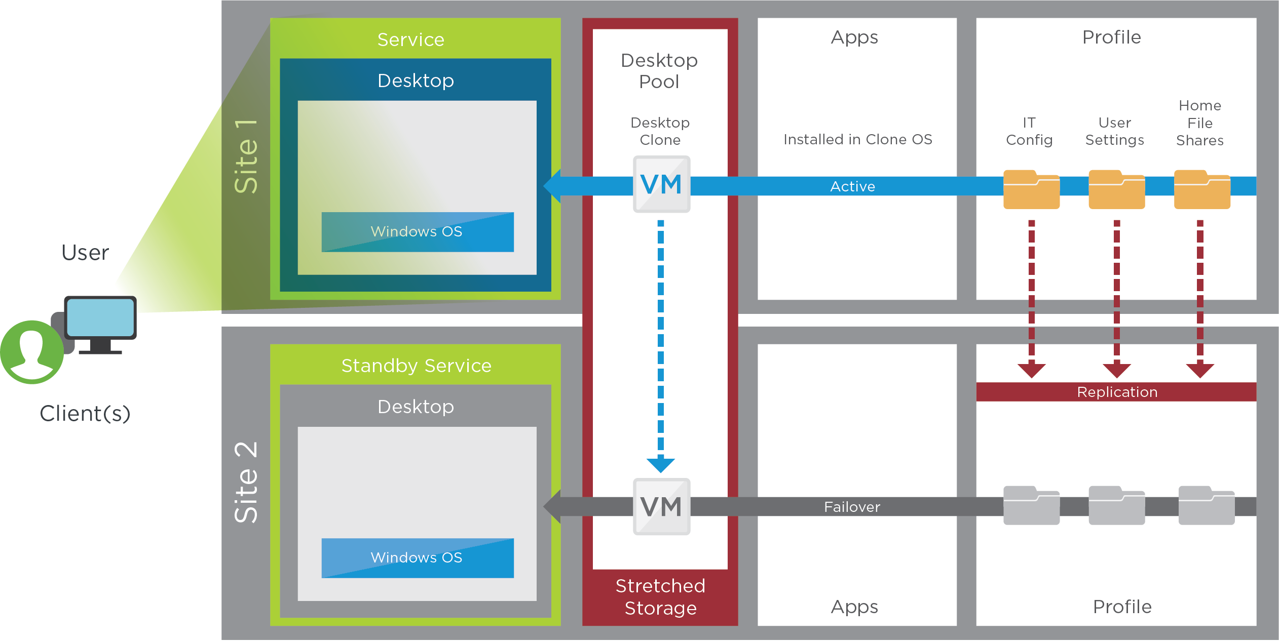
Figure 1: Blueprint for the vSAN Stretched Cluster Active/Passive Service
Architectural Approach
This architecture relies on a single Horizon pod with all required services always running at a specific site and never stretched between geographical locations. Only desktop workloads can run actively in both sites. The Connection Servers and other server components can fail over to Site 2 as a whole unit in the event of an outage of Site 1. This architecture relies on vSAN stretched cluster technology.
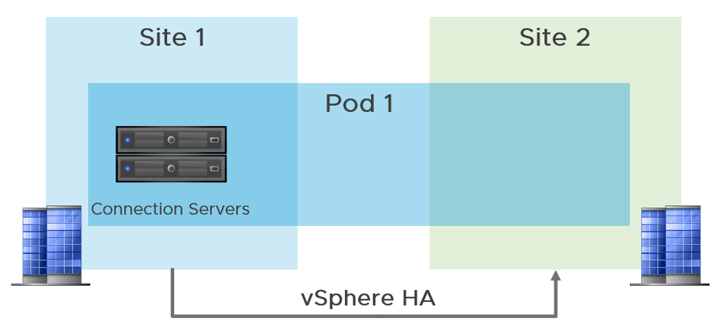
Figure 2: Stretched Cluster Active/Passive Architecture
vSphere Infrastructure Design Using vSAN
The stretched cluster active/passive service uses Horizon hosted on a vSphere environment with a vSAN stretched cluster and storage between the two sites.
In the validation of this design, a vSAN storage environment was deployed as a vSAN stretched cluster to provide high availability and business continuity for the virtual desktops in a metro cluster deployment. The vSAN stretched cluster also achieves the high availability and business continuity required for the management server VMs.
To protect against a single-site failure in a metro or campus network environment with low network latency between sites, a stretched cluster can synchronously replicate data between the two sites, with a short RTO time and no loss of data.
vSAN does support active/active data sites with desktops and RDSH VMs active in both sites. Although these virtual desktops and Horizon published applications can operate in active/active mode, the supporting management machines, and especially the Connection Servers, must all run within the one data center at a given time. To achieve this, the management servers should all be pinned to the same site at all times. Horizon management services are deployed in an active/passive mode on a vSAN stretched cluster, failing over to the secondary site in the event of a site failure.
Fault Domains
A vSAN stretched cluster is organized into three fault domains, referred to as preferred, secondary, and witness. Each fault domain denotes a separate, geographically dispersed site.
- Preferred and secondary fault domains are data sites that contain an equal number of VMware ESXi™ servers, with VMs deployed on them.
- The witness fault domain contains a single physical ESXi server or an ESXi virtual appliance whose purpose is to host metadata. It does not participate in storage operations. The witness host serves as a tie-breaker when the network connection is lost. If the network connection between the preferred and secondary sites is lost, the witness helps make the decision regarding the availability of datastore components. The witness host cannot run VMs, and a single witness host can support only one vSAN stretched cluster.
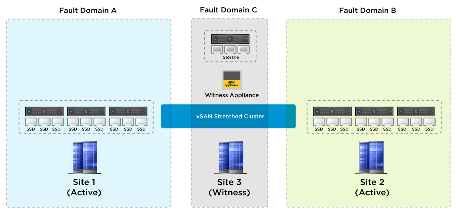
Figure 3: vSAN Stretched Cluster Configuration
In vSAN 6.6 and later releases, an extra level of local fault protection is available for VM objects in stretched clusters. When a stretched cluster is configured, the following policy rules are available for objects in the cluster:
- Primary level of failures to tolerate (PFTT) – For stretched clusters, PFTT defines the number of site failures that a VM object can tolerate. For a stretched cluster, only a value of 0 or 1 is supported.
- Secondary level of failures to tolerate (SFTT) – For stretched clusters, SFTT defines the number of additional host failures that the object can tolerate after the number of site failures defined by PFTT is reached. If PFTT = 1 and SFTT = 2, and one site is unavailable, then the cluster can tolerate two additional host failures. The default value is 0, and the maximum value is 3.
- Affinity – This rule is available only if PFTT = 0. You can set the Affinity rule to None, Preferred, or Secondary. This rule enables you to restrict VM objects to a selected site in the stretched cluster. The default value is None.
Horizon Pod and Block in a vSAN Stretched Cluster
In the validation of this design, a single vSAN stretched cluster was used for both the management block and the desktop block.
One VMware vCenter Server® was deployed for the management servers and the desktop resources.
Three ESXi hosts were deployed in Site 1 and Site 2, and a witness virtual appliance deployed in Site 3.
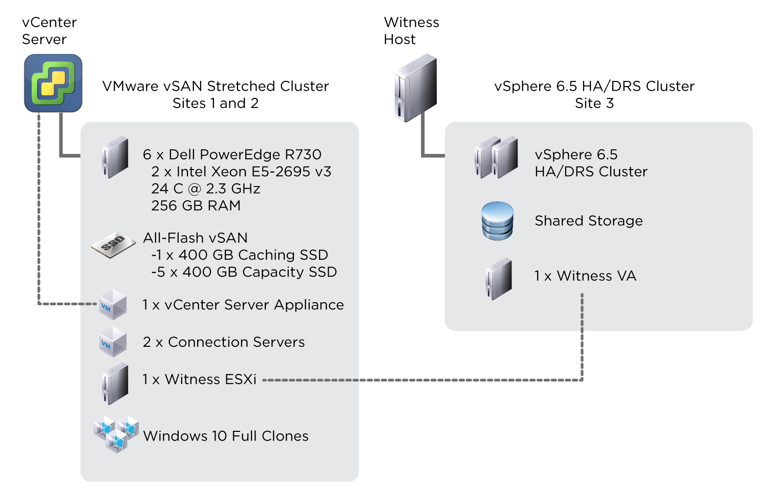
Figure 4: Horizon on vSAN Stretched Cluster
vSAN Network Requirements
Connectivity between vSAN data sites and the witness site must obey strict requirements. Both layer-2 (L2, same subnet) and layer-3 (L3, routed) configurations are used in a vSAN stretched cluster deployment.
vSAN communication between the data sites can be over stretched L2 or L3 networks, and vSAN communication between data sites and the witness site can be routed over L3.
vSAN traffic between data sites is unicast for vSAN versions 6.6 and later (multicast for versions 6.5 and earlier). Traffic between a data site and the witness site is unicast.
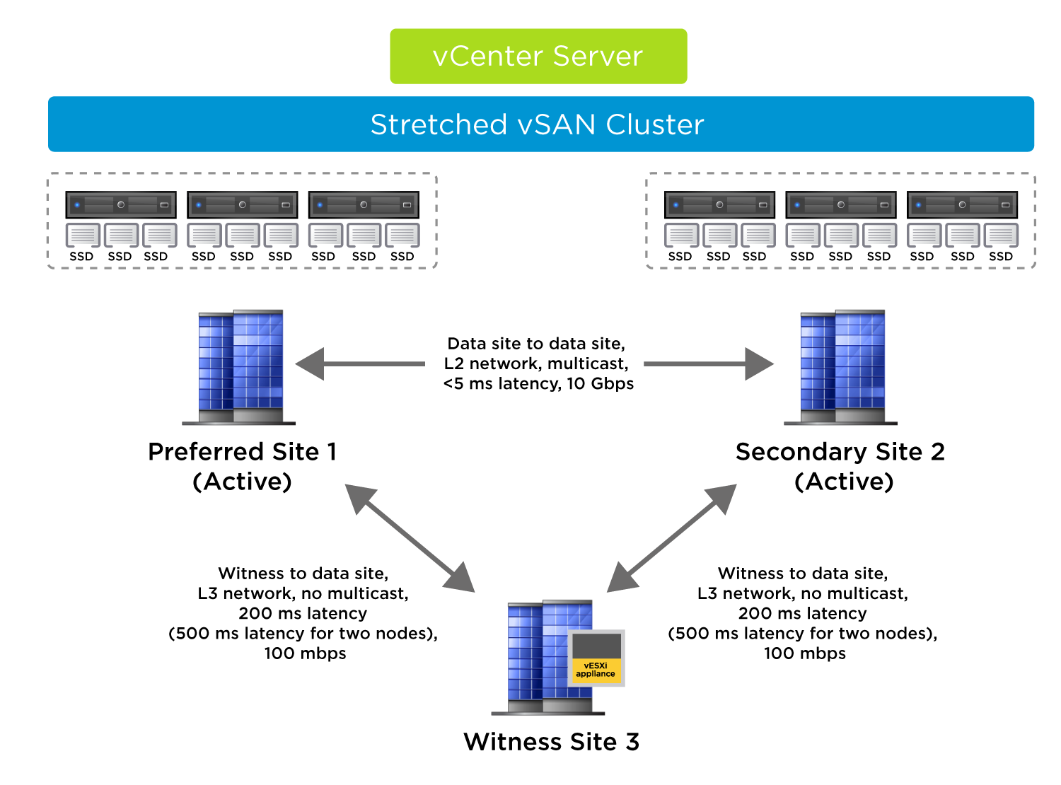
Figure 5: Networking for a vSAN Stretched Cluster
A critical requirement for a vSAN stretched cluster is the amount of latency between sites. Latency between data sites should not exceed 5 ms RTT (2.5 ms each way).
Maximum latency between data sites and the witness site depends on the number of objects in the vSAN cluster. In general, latency between a data site and witness site can be a maximum of 200 ms RTT (100 ms each way), for up to a 10+10+1 vSAN configuration (preferred + secondary + witness nodes). For configurations greater than 10+10+1, VMware requires a latency of less than or equal to 100 ms (50 ms each way).
VMware recommends having 10-Gbps network bandwidth between data sites.
Bandwidth requirements between data sites and the witness site depends on the number of components in the vSAN cluster.
For more detailed information on the required bandwidth for vSAN stretched cluster, see Bandwidth and Latency Requirements and vSAN Stretched Cluster Bandwidth Sizing.
vSphere Virtual Networking and vSAN
A single instance of VMware vSphere® Distributed Switch™ was created with two 10-Gb interfaces in a team.
Four port groups isolate network traffic:
- Virtual machines
- ESXi management network
- VMware vSphere® vMotion®
- vSAN traffic
Quality of service is enforced with network I/O control (NIOC) on the distributed virtual switch, guaranteeing a share of bandwidth for each type of traffic.
A vmkernel interface (vmknic) is created on the ESXi management port group, vSphere vMotion port group, and vSAN port group.
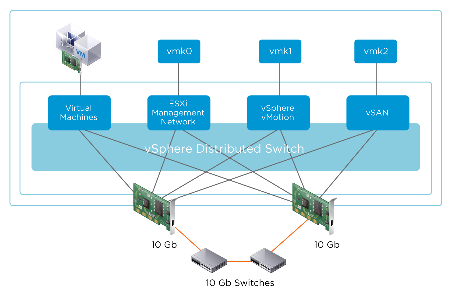
Figure 6: vSphere Networking
Example Configuration
In this example, the virtual witness is connected over L3 and static routes. vSAN data sites 1 and 2 are connected over a stretched L2 network for the management network, vSAN network, vMotion network, and VM network.
Because the physical routers do not automatically route traffic between sites 1, 2, and 3, it is necessary to add static routes so that vSAN traffic from the preferred and secondary sites can reach the witness host and vice versa. It is also necessary to add static routes so that vCenter Server can reach the management network of the witness ESXi host.
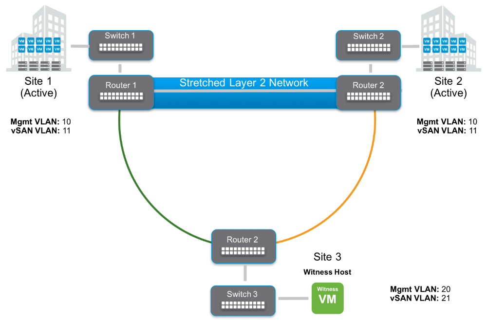
Figure 7: vSAN Virtual Witness Connected Over L3 and Static Routes
Static routes are added using esxcfg-route–a command that you run on the ESXi hosts. Run this command on all ESXi hosts in the cluster, both in the data sites and on the witness host.
Static routes:
- Site 1 data nodes (VLAN11) to witness vSAN vmkernel Site 3 (VLAN21)
- Site 3 witness vSAN vmkernel (VLAN21) to Site 1 data nodes (VLAN11)
- Site 2 data nodes (VLAN11) to witness vSAN vmkernel Site 3 (VLAN21)
- Site 3 witness vSAN vmkernel (VLAN21) to Site 2 data nodes (VLAN11)
- vCenter Server to Site 3 witness management vmkernel (VLAN20)
- Site 3 witness management vmkernel (VLAN20) to vCenter Server
Configure the physical network switches to have IP routing enabled between the vSAN network VLANs on the data sites and the witness site, in this example VLANs 11 and 21. Once requests arrive for the remote host (either witness-to-data or data-to-witness), the switch will route the packet appropriately.
For more details on network requirements for vSAN, including detailed requirements for the management network, VM network, vMotion Network, and vSAN network, see Network Design Considerations.
Prerequisites and Settings
This section provides specifications for designing the infrastructure of the active/passive service using a vSAN stretched cluster, including settings for vSAN, vSphere, distributed switches, and storage.
The following table details the vSAN prerequisites.
Table 2: vSAN Prerequisites
| Requirements | Configuration Considerations |
| Three dispersed sites | Two data sites, each with an equal number of ESXi hosts One witness site with a dedicated ESXi physical server or virtual appliance, per vSAN stretched cluster |
| Network requirements | Data site to data site:
Witness site to data site:
|
The vSphere HA settings are summarized in the following table.
Table 3: vSphere High Availability Settings
| Name of Setting | Setting to Use |
| vSphere HA | Turn on vSphere HA |
| Host Monitoring | Enabled |
| Heartbeat Datastores | Turned off (default) |
| Virtual Machine Monitoring | Turned off (default) |
| Admission Control | Set to 50% |
| Failures and Responses | Power off and restart VMs |
| Datastore Heartbeats | Select Use datastores only from the specified list – Do not select any of the datastores |
Settings for VMware vSphere® Distributed Resource Scheduler™ are summarized in the following table.
Table 4: vSphere Distributed Resource Scheduler Settings
| Name of Setting | Setting to Use |
| vSphere DRS | Turn on vSphere DRS |
| DRS Automation | Partially Automated |
| Power Management | Off |
| VMHost Groups | For management servers only: Add new VMHost Groups:
Add new VM Group:
|
| VMHost Rules | Add a new VMHost rule:
For Must run on hosts in group:
|
| vSphere HA Rule Settings | VM to Host affinity rules: vSphere HA should respect rules during failover. |
Storage Policies
For the vSAN configuration of 3+3+1, the following vSAN storage policies were used:
- Primary level of failures to tolerate (PFTT) = 1
- Secondary level of failures to tolerate (SFTT) =1;
- Failure tolerance method = RAID-1 (Mirroring).
Steps for Building vSAN Stretched Cluster Recovery Services
This section covers the high-level steps required to build out the active/passive service (using a vSAN stretched cluster), which can be seen from a blueprint perspective in the following figure.
Figure 8: Blueprint for a Stretched Cluster Active/Passive Service
The following table outlines the steps required for creating a vSAN stretched cluster.
Table 5: Steps for Configuring a vSAN Stretched Cluster Active/Passive Service
| Step | Details |
| Prerequisites | Review the Stretched Cluster Design Considerations section of What Are vSAN Stretched Clusters and ensure the prerequisites listed in Prerequisites and Settings for the vSAN Stretched Cluster Service. |
| Witnesses | Deploy a vSAN witness appliance on a vSphere HA/DRS cluster in witness Site 3. Set the static network routes, if required. Add the vSAN witness appliance to vCenter Server as a standalone ESXi host. |
| vSphere clusters | Create the required vSphere stretched cluster by adding the ESXi hosts from Site 1 and Site 2. Enable vSAN for the cluster. Configure the fault domains and select the relevant witness hosts created earlier. |
| DRS and HA | Configure DRS and HA settings as listed in Prerequisites and Settings for the vSAN Stretched Cluster Service. |
| Affinity | To pin the management servers as a unit to a particular site, you must create VMHost groups and VMHost rules. See Prerequisites and Settings for the vSAN Stretched Cluster Service for details. |
| Complete | Configure Horizon servers and the VM template for the virtual desktops. Provision Horizon full-clone desktops. |
The following table outlines the steps for creating the virtual desktops and published applications to be provided by a vSAN stretched cluster.
Table 6: Steps for Creating the Windows Component of a vSAN Stretched Cluster Active/Passive Service
| Step | Details |
| Load balancing | Verify both global and local load balancing are functional. |
| Golden Image VM | Build out a golden image VM image in Site 1 to meet requirements. |
| Create desktop pool | Create a desktop pool based on the golden image VM. |
| Entitlements | Entitle the users to the desktop pool as required. |
Note: With regards to the environmental infrastructure design, including Active Directory, distributed file systems, load balancing, and DHCP, you can use the same design as is used for the multi-site active/active and active/passive use cases, as described in Environment Infrastructure Design.
Reference Architecture Validation for the Stretched Cluster Service
This section details the impact to both users and services during failure and the behavior after failover for all the services.
Table 7: vSAN Stretched Cluster Active/Passive Service Failure Impact
| Type of Access | During Failure | After Failover |
| Logged-in user | Some sessions are terminated (depends on the location where the desktop is running). | N/A |
| New user logging in | User cannot log in. | After management services have resumed, users can log in as normal. |
| Access to user data | If the desktop is not disconnected, a full-clone user has access to data. | User has access to data. |
Test Recovery Plan
For this test, a whole site failure was simulated for one of the data sites in a vSAN stretched cluster configuration consisting of Horizon management server VMs and virtual desktops running on a vSAN stretched cluster.
Users were logged in to full-clone virtual desktops when the failure occurred.
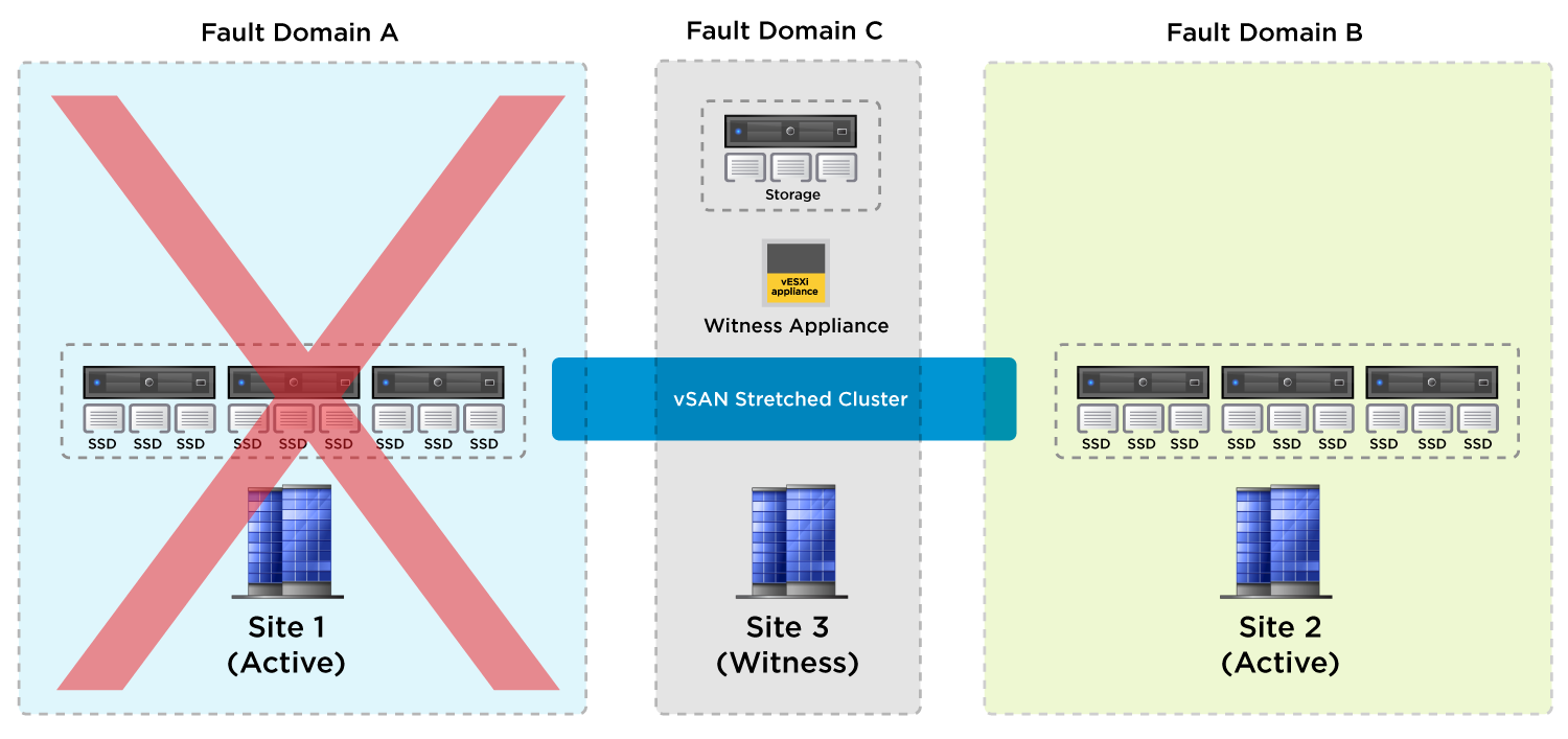
Figure 9: Active/Passive Horizon Service Failover Test/Recovery Plan on vSAN Stretched Cluster
The following table lists the preliminary tests and checks to be performed.
Table 8: Active/Passive on vSAN Stretched Cluster Preliminary Tests
| Test | Name | Description | Expectation | Outcome |
| 0.1 | Identify candidate site for simulated failure | Select the site where all management VMs are running. | Management machines are pinned to the data site using DRS affinity rules. | Site 1 selected |
| 0.2 | Verify virtual desktops are ready for test | Check full-clone pool deployed across desktop vSAN stretched cluster. | Full-clone virtual desktops are available for login across both sites. | As expected |
| 0.3 | Verify vSAN fault domain, HA, and DRS settings | Verify that vSAN is operating effectively, with no errors. Also, verify that vSphere HA and DRS are enabled and configured correctly to support vSAN site failover. | vSAN reports no issues with configuration. vSphere HA and DRS settings are optimal. | As expected |
| 0.4 | Users log in to virtual desktops | Have test users log in to full-clone virtual desktops; one in each of Site 1 and Site 2. | Users are logged in to full-clone virtual desktops in Site 1 and Site 2. | As expected |
| 0.5 | Prepare to record the time period of the failover | Prepare a timer device to record the time it takes for failover of services from Site 1 to Site 2. | Time source starts recording time when failover occurs. | As expected |
The following list of tests includes descriptions of occurrences during a vSAN stretched cluster active/passive service failover, the recovery steps required, and the test results.
Table 9: Active/Passive on vSAN Stretched Cluster Test Results
| Test | Name | Description | Expectation | Outcome |
| 1.0 | Site failure simulation initiated | Power is cut to all ESXi servers in Site 1: one server for management VMs, three servers for hosting desktops. | The ESXi server that hosts the management VMs goes offline. Full-clone virtual desktops in Site 1 are unavailable. Virtual desktop sessions to full-clone desktops in Site 1 are disconnected. Virtual desktop sessions to full-clone desktops in Site 2 are unaffected. | As expected |
| 2.0 | vSphere HA fails the management VMs over to Site 2 | vSphere HA starts up management VMs (vCenter Server, Connection Servers in Site 2. | vSphere HA restarts the management VMs within 30 seconds. | vSphere HA restarts management VMs within 25 seconds. Management VMs show vSAN storage policy non-compliance. |
| 2.1 | vSphere HA fails over full-clone desktops to Site 2 | vSphere HA starts up all full-clone desktops that had been running in Site 1 before failure occurred. | vSphere HA restarts virtual desktops. | vSphere HA powers on all virtual desktops in 2 minutes. Desktop VMs show vSAN storage policy non-compliance. |
Summary and Additional Resources
Now that you have come to the end of this design chapter on Horizon active-passive on stretched vSAN service, you can return to the landing page and use the tabs, search, or scroll to select your next chapter in one of the following sections:
- Overview chapters provide understanding of business drivers, use cases, and service definitions.
- Architecture chapters give design guidance on the products you are interested in including in your platform, including Workspace ONE UEM, Workspace ONE Access, Workspace ONE Assist, Workspace ONE Intelligence, Horizon Cloud Service, Horizon, App Volumes, Dynamic Environment Manager, and Unified Access Gateway.
- Integration chapters cover the integration of products, components, and services you need to create the platform capable of delivering the services that you want to deliver to your users.
- Configuration chapters provide reference for specific tasks as you build your platform, such as installation, deployment, and configuration processes for Workspace ONE, Horizon Cloud Service, Horizon, App Volumes, Dynamic Environment Management, and more.
Additional Resources
For more information about VMware Horizon, you can explore the following resources:
- VMware Horizon product page
- VMware Horizon documentation
- vSAN Planning and Deployment documentation
- Tech Zone vSAN landing page
Changelog
The following updates were made to this guide:
| Date | Description of Changes |
| 2023-07-25 |
|
Author and Contributors
- Donal Geary, Senior Lab Manager in End-User-Computing Technical Marketing, VMware.
- Graeme Gordon, Senior Staff End-User-Computing (EUC) Architect in End-User-Computing Technical Marketing, VMware.
Feedback
Your feedback is valuable.
To comment on this paper, contact VMware End-User-Computing Technical Marketing at euc_tech_content_feedback@vmware.com.